Facebook
 Google
 GitHub
 Linkedin
Hi everyone,
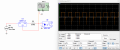
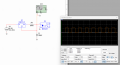
I am trying to make a circuit with lm317 to have a constant current. I would like to use it with both a constant voltage generator and a pulsed voltage generator. Now if I simulate this circuit I get these spikes (circuit 1). If I add capacitor C1 with a value >=300pF the disturbance disappears (circuit 2). I believe capacitor C1 composes a low-pass filter at about 2.1 Mhz but I do not understand why without it the visible spike in circuit 1 occurs.
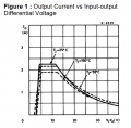
I also cannot get down to 3.3V input with either a pulsed or continuous generator. I do not get the expected 5ma output from the regulator.
Can anyone help me with this?
I am trying to make a circuit with lm317 to have a constant current. I would like to use it with both a constant voltage generator and a pulsed voltage generator. Now if I simulate this circuit I get these spikes (circuit 1). If I add capacitor C1 with a value >=300pF the disturbance disappears (circuit 2). I believe capacitor C1 composes a low-pass filter at about 2.1 Mhz but I do not understand why without it the visible spike in circuit 1 occurs.
I also cannot get down to 3.3V input with either a pulsed or continuous generator. I do not get the expected 5ma output from the regulator.
Can anyone help me with this?
Attachments
-
 42 KB Views: 32
 -
 48.9 KB Views: 31