LM317 SHORT CIRCUIT / OVERCURRENT INDICATOR

Thread Starter

Fnordgasm5

Joined Mar 2, 2013
15
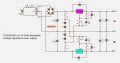
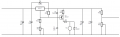
Can anyone tell me if this will work please? Basically I need the relay to de-energise in the event of a short circuit or and overcurrent event which will then switch an LED and / or a buzzer (not shown). As I understand it the LM317 will attempt to maintain a voltage of 1.25V between the output and the ADJ terminals and in the event of a short between the GND and output or anything else that causes excess current this voltage will drop but I'm not 100% sure on that. I've also added a zener in series with the relay coil of the same voltage with the intention de-energising said relay when the voltage from the output drops. Does this look right?
 

Attachments

Deleted member 115935

Joined Dec 31, 1969
0
Uhm, Im not going to answer , but I will try to help, if thats not an oxymoron !

Your schematic, what was it drawn in ? Its usual to have dots where wires join , no dots where they dont. and its unusual to have wires crossed and connected, All of which the schematic does which make the schematic ambiguous,

What sort of output current to the load are you expecting ?
You are showing the output as through a 1k5 / 6k ohm voltage divider, which is going to seriously limit the output current, divide the voltage delivered by the 317, and make the output voltage dependent upon current drawn, which is opposite of what I guess you expect from a 317.

so what are you trying to do this for ?
there are many circuits around that make a power supply,
you can have modes that either
if over current,
a) the voltage goes back to "zero"
b) the voltage drops to keep current constant
 

Thread Starter

Fnordgasm5

Joined Mar 2, 2013
15
Yeah, sorry the drawing was bit of a rush job on Autocad (which I've only been using a week). There are no wires that "cross". Wherever the cables meet they are connected. The LM317 is supposed to provide a constant voltage with VR1 simply there to calibrate the voltage. the voltage divider and VR2 are to provide a 0-12V output in this instance however the output voltage and current have yet to be finalized and accuracy isn't that important.
 

crutschow

Joined Mar 14, 2008
34,285
ZD1 is not needed,since there is a constant current of about 3mA through Q1 due to R3, independent of the output voltage.
 

Deleted member 115935

Joined Dec 31, 1969
0
Two things,

What do you want to do with R4/VR1 ?

Auto cad is not for drawing schematics.
 

Thread Starter

Fnordgasm5

Joined Mar 2, 2013
15
Two things,

What do you want to do with R4/VR1 ?

Auto cad is not for drawing schematics.
R4 / VR1 (that actually should say VR2, must fix that) is to provide a 0-12V output. I know you can use the LM317 as a variable suppy but it has a minimum output of 1.25V and I need 0V. I'm also constrained in how many ICs I can use.

It was either autocad or paint since that's all I have access to.
 

Dodgydave

Joined Jun 22, 2012
11,285
Put a Series resistor in the positive side, and put the Pnp Q1 across it, so that when the maximum current is reached it will turn on and then trip the relay or buzzer, the value of resistor will depend on you current limit,.

Example 0.7V / 10 ohms is 70 mA trip.
 

Thread Starter

Fnordgasm5

Joined Mar 2, 2013
15
Hey guys, thanks for all your help. I'm going to work out how much current I can draw from this and how much I need and adjust the resistor values accordingly. I'm almost sure I know what I'm doing
 

Thread Starter

Fnordgasm5

Joined Mar 2, 2013
15
The output resistor divider, what happens to the output voltage as the current drawn changes, Put in say 1 mA and 100 ma,

have a search, e.g.

https://kevinwidjaja21.wordpress.com/2015/12/25/make-lm317-go-down-to-0-v/
Thanks, I'll do some calculations and look some more into it. I must admit my google-fu is lacking. I thought I'd checked every variation of a LM317 circuit I could find but I've not seen that one. I did find this one (attached) but I couldn't figure out why VR1 and VR2 connect to R1 and R3 but now I see how it allows the LM317 to go down to zero. I do also need to provide a -12-0V supply so I'm thinking I get rid of the voltage divider at the output, get rid of the zener, keep the PNP transistor and relay more or less the same ( I still need to calculate the various currents around that so there may or may not be some more resistors to add). Just so I'm clear, am I correct in thinking that when excessive current is drawn from the LM317 the voltage between the output and the ADJ drops? That's what I'm inferring from "fig. 2 load regulation" of the datasheet ( https://www.ti.com/lit/ds/symlink/lm317.pdf ) and that's what I'm counting on to drive the transistor energising the relay but I'm still not sure I'm reading it correctly.

Speaking of google-fu, you know those pushbuttons where there's several of them in a line and you can only have one pressed in at a time and when you press another the other button pops up? I'm sure there's a proper name for them but I've typed dozens of search terms into google and I can't find what I'm looking for. Any idea?

Also, any reccommendations for software for drawing circuits? At the moment I've got paint and autocad and neither really suitable.

Again, thanks for your help. I think I'm on the right track. It is much appreciated.
 

Attachments

Top