LM2907 problems. I cannot make it working. Always display 0 on voltage.

Status
Not open for further replies.

Thread Starter

davidbr

Joined Apr 25, 2018
60
Hello all,
This is my first post here and please be gentle if I do some mistakes :)

So my problem is :
I want to measure speed of 2 wheels using arduino.
Maximum speed which is not possible to reach is about 6.6 km/h , which means around 700 rpm and 12Hz as frequency.
Minimum speed which I want to measure is around 60 rpm which is 1Hz. So whatever is below 1Hz I will consider "0".
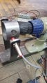
Wheel has 25mm radius, and has on it 4 oles, each 2 holes opposite. Basically I need 4 pulses for a complete revolution.
For getting pulses I am using a proximity sensor which has 12V pulse when is on the whole and 0V when is not on the hole.
The wheel and sensor pictures are attached
I tried schematic from datasheet and also tried this schematic as well http://bettec.info/dro/
On both I get only 0 at the output no matter the rpm is...

Thanks you in advance
 

Attachments

mcgyvr

Joined Oct 15, 2009
5,394
Do have an actual true/proper schematic showing exactly how YOU have it wired/powered to your arduino.?
Not someone elses.. What you actually have..
 

Thread Starter

davidbr

Joined Apr 25, 2018
60
I haven t yet wired to arduino, I just measured voltage between output of LM and ground.
I tried 2 versions, first is one from this link http://bettec.info/dro/ (variant with 8 pin LM) and second the one from datasheet from minimal tacho example.
If is working then voltage should vary if i speed up the wheel...so as long I have 0.02V all the time I am assuming that my circuit will not work..
Or maybe I misunderstood your question?
 
Last edited:

dendad

Joined Feb 20, 2016
4,451
Do you get the internal LED on the proximity sensor (prox) working?
This prox is probably an open collector type so....
The prox most likley needs a pullup resistor to work so add a 2K2 resistor between the + and output then see if you get pulses. For running into an Arduino, connect the pullup from the output to the +5V supply, not the prox supply. Ensure the pulses to the Arduino do not go over 5V.
And it will work better with more pulses per turn I think. The response will be smoother.
 

Thread Starter

davidbr

Joined Apr 25, 2018
60
Hi,
The led on the sensor is working. While output is 0V the led is on and while output is hight(sensor is in hole) the led d off.
I will try add pull up resistor on the sensor output...
 

mcgyvr

Joined Oct 15, 2009
5,394
I haven t yet wired to arduino, I just measured voltage between output of LM and ground.
I tried 2 versions, first is one from this link http://bettec.info/dro/ (variant with 8 pin LM) and second the one from datasheet from minimal tacho example.
If is working then voltage should vary if i speed up the wheel...so as long I have 0.02V all the time I am assuming that my circuit will not work..
Or maybe I misunderstood your question?
You can't test it that way..
Its an open collector (NPN) and needs to be interfaced properly..
Sounds like its working you just aren't doing a suitable test
 

Thread Starter

davidbr

Joined Apr 25, 2018
60
You can't test it that way..
Its an open collector (NPN) and needs to be interfaced properly..
Sounds like its working you just aren't doing a suitable test
And which will be a good interfave and proper test?
Yes, sensor is npn
Thanks
 

dendad

Joined Feb 20, 2016
4,451
Why are you using an LM2907 FtoV converter when the Arduino can be used to measure the pulse frequency or period?
It is just a thought,
I supose measuring a voltage is a bit easier.
 

Thread Starter

davidbr

Joined Apr 25, 2018
60
Ok,
Attached is the schematic that I did, and I followed exactly the values from here (lm2907.png).
The sensor is wired like this : Brown to +12V, Blue to GND and Black to PIN1 of LM.

I measure between +Vout and GND.

I tried also with 2k2 resistor between Black and Brown of the sensor and get same result.
What I am thinking is why on the schematic is on +Vout value 67Hz /V ? In my tests I don t think I go up about 10 Hz ...maybe I should use different values on components?

Thanks again
 

Attachments

Thread Starter

davidbr

Joined Apr 25, 2018
60
I cannot edit but I saw that in first post i made a mistake:

"Maximum speed which is not possible to reach is about 6.6 km/h , which means around 700 rpm and 12Hz as frequency.
Minimum speed which I want to measure is around 60 rpm which is 1Hz. So whatever is below 1Hz I will consider "0"."
Considering I get 4 pulses for revolution that means my freq are between 4Hz and 48Hz not like I said in first post
 

bertus

Joined Apr 5, 2008
22,270
Hello,

There is no resistor needed from the brown to black, as there is a 4k7 resistor in the sensor.
Do you see pulses at the output of the sensor?
The datasheet shows me that the sensing distance is 4 mm for your sensor.

Bertus
 

Attachments

Thread Starter

davidbr

Joined Apr 25, 2018
60
I am talking about sensor led which is on when I have sensor out of the hole and 0 on output. When sensor is in hole, then led is off and I have 12v on output
see picture
 

Attachments

Status
Not open for further replies.
Top