LM2576 supply voltage oscilating under small loads

Thread Starter

electro63

Joined Dec 2, 2021
10
Hello,
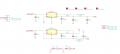
This is my first message on this forum. I am making a dual power supply -12V +12V based on LM2576. The schematic is based on the constructor datasheet. Everything works fine if the current load on the +12V does not exceed 500mA (approximately). When the load current exeeds 500mA at the +12V, the supply voltage (from a bench power supply at 15V limited at 6A) starts oscilating: 1Volt amplitude at around 33Hz , the waveform is a kind of smooth sawtooth). The +12V is stable, just the supply is oscillating. It seems the -12V doe not generate this problem, it works fine at least untill 600 mA (did'nt test it on loads superior to 600mA).
Any idea about what is happening ?
Thank for your help.
 

Attachments

Papabravo

Joined Feb 24, 2006
21,159
If I read your schematic correctly you have a buck converter with a duty cycle that exceeds 50%. In this configuration there is a known behavior called sub-harmonic oscillation where the IC is having trouble regulating the voltage and supplying the desired current. I don't have a datasheet handy but early chips did not have a feature known as "slope compensation" to mitigate this problem. I admit that 33 Hz. sounds a bit low for this behavior, I won't know until I can get my hands on a datasheet.

EDIT: Isn't it true that the datasheet characterizes the part with a 12 volt output using 25 Volts for Vin, when Iload is less than 0.5 amps? You don't suppose there is a reason for that, do you? I do see where Vin can be 15V to 40V when Iload is between 0.5A and 3.0A

EDIT 2: Never mind the earlier duty cycle comment. The datasheet says it can go up to 98% when the feedback pin is removed and connected to 0 volts. Which begs the question about the limit with the FB pin connected.

EDIT 3: In the functional block diagram in §7.2 of the LM2576 datasheet (TI-2021) there is no mention of slope compensation, so that could still be a problem at low current or when the 2000 uF output capacitor (twice as big as the reference design) cannot get rid of it's charge during the discharge cycle.

It might be beneficial to get some ice-time on a simulator for this one.

Q: Did you calculate the required values for the main inductor and the output capacitor, or did you just decide that bigger was better?
Q: What is the ESR of the 2000 μF capacitor?

As an aside I'm going to guess that the addition of a pi-filter is not doing much for you to reduce the output ripple.
 
Last edited:

Thread Starter

electro63

Joined Dec 2, 2021
10
@Papabravo, following your first edit suggestion I tried to rise Vin to 25V and it is still oscillating. Nevertheless when Vin is 26V it works fine, not oscilating anymore. And more over, if I start with Vin at 26V, I can then go down to 15V without any problem. But if I turn off the supply and start it again at 15V Vin is oscillating again. So it looks like the circuit needs more current or voltage only at startup. I rised the current limit to 10Amp on my bench supply for if case there was a need for more current at startup. But didn`t solve anything. I 'm gonna read the datasheet again to see if I missed something. Do you have any idea what's happening?
 

Papabravo

Joined Feb 24, 2006
21,159
Oscillations happen because there is an undamped RLC circuit. It is not always obvious which components, or parasitic elements of those components, are causing the problem. In a buck regulator the thing that connects Vin to Vout is the inductor, and it has a low impedance for low frequency oscillation. If I were you I would go back and start with the switching frequency and re-compute the necessary value for the components. Then start looking for the combinations that could cause the problem.
 

ElectricSpidey

Joined Dec 2, 2017
2,758
Sounds to me like something that happens very often, that being the converter and the supply don't get along.

Is the supply linear or SMPS?

Have you tried placing a larger cap on the output of the supply?
 
Last edited:

Thread Starter

electro63

Joined Dec 2, 2021
10
I realized that If I power up the converter without load and then connect the load it works fine. As well as I realized that if at startup the supply is at least 26V I can down down after start up , I go down to 15V. So I guess the problem is at start up time... The datasheet shows a delayed startup circuit. I'll try it.
In the meantime I tried with another power supply and it works fine with the new one. So for the moment I stick to the new psu for my tests.
 
Top