LM1881 output drops when connected to dsPIC 3.3V

Thread Starter

tom66

Joined May 9, 2009
2,595
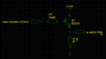
Normally the LM1881 shows a 4.4V output on my 'scope when a pin is high. However, when connected to my dsPIC it sinks to a low 1V, too low for the dsPIC to consider it as a logic high. Short of using complicated interface circuitry (thinking of a transistor here) how can I get the output to go within reasonable levels? Why is it sinking?

I am using 5V tolerant IOs with a dsPIC33FJ128GP802 in a DIP-28 package, and a LM1881 from National Semiconductor.
 

SgtWookie

Joined Jul 17, 2007
22,230
I kind of hate to ask the obvious question, but have you looked at the output specifications in the datasheet for the LM1881?
 

Thread Starter

tom66

Joined May 9, 2009
2,595
As far as I can see in the datasheet there are no typical high or low output voltages, but I am powering it from ~5.17 volts and the high voltage is ~4.6 volts so this makes sense (it's 0.57 volts dropped, for <1 mA through the output transistor this sounds right.)

I ended up using a simple transistor circuit but I would like to know if I can remove this because it would make my circuit smaller and I am putting this on an RC plane so size is a concern.
 

SgtWookie

Joined Jul 17, 2007
22,230
Look at the input capacitance of the PIC, and calculate how long it would take to charge/discharge that input. You don't specify which output(s) you are using.

I don't see your schematic or board layout, so it's tough to make guesses about why you're having that problem.
 

Thread Starter

tom66

Joined May 9, 2009
2,595
The LM1881 has a maximum output frequency of 15.625 kHz with a PAL video input. I am not particularly worried about speed, that is why I am building it on a solderless breadboard. On my 'scope, looking at the waveform of CSYNC for example, when the dsPIC was not connected, the output started at 4.8 volts then fell to 4.6 volts after about 1µs (some kind of overshoot.) Rise time was relatively high with and without the dsPIC, about 50ns, probably due to the chip itself.

My board layout is very simple, the LM1881 is connected directly to the dsPIC. (Well for now I have it connected through a transistor circuit which is working but I am keen to see if I can remove this.)
 

SgtWookie

Joined Jul 17, 2007
22,230
Solderless breadboards have lots of parasitic inductance and capacitance. You'd be better off to do a "dead bug" or wire-wrap prototype.
 

Thread Starter

tom66

Joined May 9, 2009
2,595
I am putting a colour PAL video signal through it which requires at least 3 MHz bandwidth for the colour burst. I am also getting a 38 MHz clock on the CLKOUT pin of the dsPIC which is close to a ground lead. So I don't think parasitic capacitance is a problem in this application. I think it's more likely something to do with the input of the dsPIC requiring a high current with 5V IO, but I'm not sure.
 

BMorse

Joined Sep 26, 2009
2,675
I am putting a colour PAL video signal through it which requires at least 3 MHz bandwidth for the colour burst. I am also getting a 38 MHz clock on the CLKOUT pin of the dsPIC which is close to a ground lead. So I don't think parasitic capacitance is a problem in this application. I think it's more likely something to do with the input of the dsPIC requiring a high current with 5V IO, but I'm not sure.

Are you sure the ADC input of the dsPic is 5 volt tolerant? Most of these 3.3 volt devices I know off can tolerate 5 volts on a Digital I/O, not on the ADC pins!!

quote from datasheet:
• All digital input pins are 5V tolerant
B. Morse
 

Ron H

Joined Apr 14, 2005
7,063
Using a BC635 NPN, because I have about 50 in my parts box.

Don't know the name, but here's a quick schematic.
That circuit can overwhelm a pin that is configured as an output. You need to make sure Rb6 is configured as an input. If it's not, you won't be able to read the pin, even if you can drive it.
 

Thread Starter

tom66

Joined May 9, 2009
2,595
It is set up as an input because the pin is synchronised to the signal.

The problem is can I eliminate or reduce this circuit, just feeding the output from the LM1881 to the dsPIC. So far, it seems not...
 

Thread Starter

tom66

Joined May 9, 2009
2,595
Ok, today is getting kinda weird.

I was having trouble with the transistor circuit I posted... slow fall time, about 2.5 µs. So I decided to remove components one by one, wiring the 5V output straight to the 3.3V dsPIC (into a 5V IO)... and now it works perfectly??! That's just annoying, but at the same time great!
 
Top