Perhaps you could clarify, where is the control voltage coming from, for example is it something like zero to 5 volts coming from the center tap of a potentiometer connected between the suppl and ground, and what are you wanting the current to flow through and is that load connected on one side to the positive rail or ground?
I have been studying Christophe Basso's feedback loop design. He has designs with OTA and I found lm13800 on Proteus so I thought I could use it. I replaced a generic current source instead op amp which worked fine but It would be great if I can bias and use lm13700.
hi myil.
I have the LM13700 LTspice model that I use.
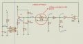
Post your basic circuit and the required project specification and I will create a sim circuit.
E
hi myil.
I have the LM13700 LTspice model that I use.
Post your basic circuit and the required project specification and I will create a sim circuit.
E
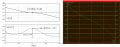
Input voltage 0 to 5V.
Output voltage 0 to 100 amps. (mA, uA??)
What is the load like. Resistive load to ground? (5 ohms sitting on ground?)
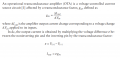
This information is important. This circuit translates the voltage from IC2 to current in the load.
Input voltage 0 to 5V.
Output voltage 0 to 100 amps. (mA, uA??)
What is the load like. Resistive load to ground? (5 ohms sitting on ground?)
This information is important. This circuit translates the voltage from IC2 to current in the load.
Hi ronsimpson,
Thank you for your reply. I think the idea behind it is that OTA should work as a current source depending on the difference between its negative and positive inputs.
Hi DickCappels,
Thank you for suggesting Howland current source. I removed the current source from the design and added the Howland current source. That works great as the generic current source in the database. But I am little bit sad that I couldn't make lm13700 work. I tried to contact with Texas instruments but sadly they didn't offer any support but pointing me to read datasheet.
 Facebook
 Google
 GitHub
 Linkedin


")