 Facebook
 Google
 GitHub
 Linkedin
Dear all,
I am new to the forums and have searched existing posts, but could not find a solution to my problem.
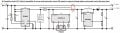
I am developing a Charger Circuit for LiPo single cell batteries from existing ICs (Please see attachment for my current progress).
The circuit seems legit to this point, however I would like to add the following feature: When the USB 5V power supply is connected, the boost converter should be deactivated (no need for boosting with connected USB), while the battery should be able to charge and the load should be supplied at the same time by the USB supply.
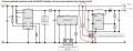
I have tried to implement this using a MOSFET to switch off the boost circuit when 5 V are supplied via connected power cable (see attachment, figure 3). However, I am unsure whether this will work out... The Vout (+5V) pin should in this case be merged or identical with Vboost, unsure how to achieve that, in order to avoid a manual switch.
Is there a more adequate solution? I would like to avoid using expensive ICs and try to use analog designs with MOSFETs if possible and not too voluminous on PCB (smal form factor desired).
Any kind of input would be highly appreciated.
Another question I have: What is the exact function of the FS8205 double MOSFET? I am confused why the drain of the MOSFETS is BETWEEN the two MOSFETS. I understand the sources have to be connected to the ground, but where is the load that should be connected to the drain by definition?
Thank you all in advance!
I am new to the forums and have searched existing posts, but could not find a solution to my problem.
I am developing a Charger Circuit for LiPo single cell batteries from existing ICs (Please see attachment for my current progress).
The circuit seems legit to this point, however I would like to add the following feature: When the USB 5V power supply is connected, the boost converter should be deactivated (no need for boosting with connected USB), while the battery should be able to charge and the load should be supplied at the same time by the USB supply.
I have tried to implement this using a MOSFET to switch off the boost circuit when 5 V are supplied via connected power cable (see attachment, figure 3). However, I am unsure whether this will work out... The Vout (+5V) pin should in this case be merged or identical with Vboost, unsure how to achieve that, in order to avoid a manual switch.
Is there a more adequate solution? I would like to avoid using expensive ICs and try to use analog designs with MOSFETs if possible and not too voluminous on PCB (smal form factor desired).
Any kind of input would be highly appreciated.
Another question I have: What is the exact function of the FS8205 double MOSFET? I am confused why the drain of the MOSFETS is BETWEEN the two MOSFETS. I understand the sources have to be connected to the ground, but where is the load that should be connected to the drain by definition?
Thank you all in advance!
Attachments
-
 68.8 KB Views: 12
 -
 86.8 KB Views: 12


