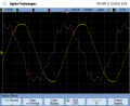
Line Voltage Very Flat Topped, What Is Yours?

Thread Starter

MrAl

Joined Jun 17, 2014
13,751
My AC line voltage look like this

View attachment 150463

50Hz 230V RMS.
Hi,

Thanks for posting that. So i see yours is a little flat topped too.

It looks like you used a USB scope there, and if so, what did you use on the input of the scope to make the measurement? Did you use a 100:1 probe for example, and where did you connect the ground lead?

Thanks much for this.
 

Thread Starter

MrAl

Joined Jun 17, 2014
13,751
Voltage samples for below image is captured with Arduino UNO ADC with about 2 kHz sampling rate. Small voltage transformer module (bought from Ebay) was used to reduce 230 VAC to ADC. Location is Helsinki, Finland.

View attachment 150473

Hi,

Thanks for the graph as well as the location. It's interesting to see the different voltages but knowing where they come from helps too. Location might have a lot to do with this.

It looks like yours isnt too bad, almost a pure sine.
I guess you used a transformer for isolation right?
 

Jony130

Joined Feb 17, 2009
5,598
It looks like you used a USB scope there
No. I was using the RIGOL DS1052e scope.

what did you use on the input of the scope to make the measurement? Did you use a 100:1 probe for example, and where did you connect the ground lead?
I simply connected the scope ground lead to neutral wire and probe tip to the live wire (I know, I behaved very irresponsibly, but at least I know what I was doing).
To be safe I should use two channels and made a differential measurement and the math function.
 

Avid0g

Joined Apr 1, 2018
21
I am retired now, but once worked for Prime Computer, a super-minicomputer company. Every time I visited a client, the power waveforms I recorded were flat-topped.

Perhaps this is just what happened at large computer sites, but the neutral current was usually about 70% of the 3-phase current at the service entrance. Huge 3rd harmonics.
 

kubeek

Joined Sep 20, 2005
5,796
To be safe I should use two channels and made a differential measurement and the math function.
Then you would connect the two ground leads to PE, or leave them unconnected and rely on the PE being connected to the scope ground anyways? First case creates ground loops and possible large currents through the shield, second case seems a bit better, but will have big issues at high frequency (lets say we extend this to the same kind of measurement at a few tens of khz and more).
A proper differential high voltage probe (albeit still a resistive divider and not a truly isolated probe) should be the choice to do such a measurement. (or a resistively loaded transformer that will for sure not saturate, but the winding capacitance might still muffle the HF content of the garbage on the power line)
 

kubeek

Joined Sep 20, 2005
5,796
I am retired now, but once worked for Prime Computer, a super-minicomputer company. Every time I visited a client, the power waveforms I recorded were flat-topped.

Perhaps this is just what happened at large computer sites, but the neutral current was usually about 70% of the 3-phase current at the service entrance. Huge 3rd harmonics.
That sounds exactly like no power correction what so ever, and large capacitive loads behind a full bridge rectifier. I remember in the "old" days when I was just before high school, that if you pushed the safety turn-off button then all the PCs in the lab would have to be manually disconnected and then connected back one by one, as they had no PFC and the inrush surge was huge, unlike the modern active PFC supplies.
 

Thread Starter

MrAl

Joined Jun 17, 2014
13,751
No. I was using the RIGOL DS1052e scope.


I simply connected the scope ground lead to neutral wire and probe tip to the live wire (I know, I behaved very irresponsibly, but at least I know what I was doing).
To be safe I should use two channels and made a differential measurement and the math function.
Hi,

Oh ok, i was going to ask how you did it because i was thinking of trying this at one point, but with a USB scope. I've read about ways to do this but dont like any of them :)
 

tsan

Joined Sep 6, 2014
141
Hi,

Thanks, any schematic available?
ACS712 module for microcontroller use is available for example on Ebay. Example result of search term "ACS712 Arduino",
https://www.ebay.com/itm/New-design...803905&hash=item484ba84020:g:5vYAAOSwRgJXkHOe

It is really easy to connect this to Arduino UNO ADC, which has a 5 V ADC range and 5V VCC available for ACS712. ACS712 can measure DC too, but it has no value on AC measurement. ACS712 modules only go up to 30 A peak, which is too small for many home appliance starting current measurement. Current transformers can measure for example 100 A, but it requires some interface or bias circuit to connect to ADC. Perhaps a few resistors and capacitors are enough. 30 A peak was ok for refrigerator, but way too little for vacuum cleaner starting current.

I used both voltage and current sensors in order to calculate power, so it was necessary to have correct phase shift between voltage and current samples. I used a water kettle as a resistive test load. Without phase shift correction, active power (voltage sample x current sample) had negative values. When delaying one of the signals a few samples, actual power was always positive (or near zero) which is correct for resistive load.
 
Using a scope with trace math, the derivative of the line waveform can be displayed. It should be a perfect sine wave if the grid waveform is a perfect sine wave to start with. Here's the grid waveform and its derivative in Washington state's Puget Sound region:

scope_0.png
 

Thread Starter

MrAl

Joined Jun 17, 2014
13,751
Using a scope with trace math, the derivative of the line waveform can be displayed. It should be a perfect sine wave if the grid waveform is a perfect sine wave to start with. Here's the grid waveform and its derivative in Washington state's Puget Sound region:

View attachment 151478

Hi,

Hey thanks, very interesting idea. My newest scope does not have derivative (strange yes) but i could always make a simple differentiator circuit and use that i guess and do a little math on the captured waveform. Here the line is 60Hz so that's a nice low frequency to work with.

I guess it looks bad near zero too, but i suspect the peak has more influence for running appliances because the most energy is nearest the peak. Thus, i hate to see a flat top.

I also have to wait for the dead of summer to test the line some more because that's when it really gets bad. I have to wonder for now if it is just the peak that goes flatter or the whole wave reduces in amplitude. I'll know in a few months when it gets really really hot outside as that is when it is the WORST i've ever seen in my life anywhere i had lived in the past (voltage goes very low for a few seconds and appliances turn off).
 

-live wire-

Joined Dec 22, 2017
959
I think they may have not stepped the voltage up enough across the power lines. Maybe they decided to just transmit 120VAC over many miles. You never know. ;)

I have a natural gas generator that outputs the worst power. It varies from 59 to 62 Hz, which my appliances are not a fan of. I think someone didn't design their inverter properly. Maybe it varies based on the voltage being generated, or possibly even the load. Or the frequency is directly influenced by some mechanical thing. Either way, it is very unreliable. The frequency is the least of the problems.

There are sometimes huge power surges when it starts up or turns off. The regular power went out, came back, and went out again. The generator tried to start up but there was too big of a load. It seemed to be mechanically incapable of starting up. But when it tried, it created huge overvoltages and failed. Many times! I had to turn the power off for everything, start it up, and turn it back on. Unfortunately, a few things did not survive this. RIP garage door control board.

And I do not even have a scope to check it. I am sure I would just be more disappointed. But at the end of the day, I get to turn all my (LED) lights on really bright and power all my appliances while my neighbors have no power. It at least works well enough for that. And the voltage is generally stable enough once it gets going, even with relatively large loads. So it was still a worthwhile investment.
 
Top