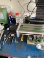
Limit switch on a ZK-SMC 02 controller

Thread Starter

Dells

Joined Sep 21, 2023
33
If you use the forward and reverse push buttons to traverse the table you would have to find a way to break the path to to push buttons to implement limit switches. On the table feed I built for my mill (A seig X3) I use a three position center off toggle switch for direction, a potentiometer for speed and a push button to do a fast traverse without having too change the speed setting. you can use the push buttons in two ways (Depending on how you configure the controller.) One way is you hold you button pressed to cause thr motor to rotate. The other ids apress of the button starts the motor and it rotates until the stop button is pressed.
Can you tell us how you want it to behave ?

Les.
I don’t mind adding a forward/off/ reverse switch all I want to do is traverse one way then back perhaps faster on way than the other so slower for the cut then faster back ready for next cut that can be done in the controller, the reason for motorising the X axis is that I struggle with holding and turning a handle due to my dodgy hands , I don’t want to hold a button down due to the same reason.
 

LesJones

Joined Jan 8, 2017
4,511
This is how I described the direction switch and limit switch connections in post#15
scan001.jpgThis is part of page 4 showing the connections
Screen Shot 04-12-24 at 08.19 PM.PNGSelect Work mode F-01->P02 from the Work mode table on page 2 of the manual.

Les.
 

Thread Starter

Dells

Joined Sep 21, 2023
33
Thanks for that Les although I am not using the driver as it’s not able to handle enough amps so have removed it but the connections should be the same here is a picture of the controller with the driver removed.
Thanks for your help Dell
IMG_2484.png
 

LesJones

Joined Jan 8, 2017
4,511
It should work the same using an external stepper driver. It seems an expensive way to just use it's function as a variable frequency oscillator.
I don't think it will be possible to add a push button to give a fast traverse function.

Les.
 

Thread Starter

Dells

Joined Sep 21, 2023
33
I will be happy if I can use it forward and back I can alter the speed with the pot on the front of control
 

LesJones

Joined Jan 8, 2017
4,511
Here are some picturs showing how I have mounted the limit switches on my mill.
IMG_1945 (Large).JPG

IMG_1947 (Large).JPGOn my mill there is a T slot along the front of the table so have mounted the cams that operate the limit swithes on the T slot. The cams also have adusting screws to form a mechanical against the pice of metal mounted between the limit switches. I use these when moving the table by hand to stop in accurate positions when milling a slot of a fixed length. The cams have a small chamfer on the bottom edge to mate eith the rollers on the micro switches.
The picture below shows how I mounted the feed motor and was taken when I first fitted it.
PICT0012.JPGI thought these pictures might give you some ideas.

Les.
 

MisterBill2

Joined Jan 23, 2018
27,587
On my small mill I use conventional milling most of the time , I seem to get better results but I do use climb milling sometimes and the tool is always moved off part before traversing the other way.
Les Jones
Not sure what you mean by connecting to forward/ reverse as the controller already has forward & reverse can you explain further please, sorry but this 70 year old head is struggling to understand.
Dell
My reference is to the suggestion made in post #15, which I see as suggesting an automated instant reversal of travel.
 

Thread Starter

Dells

Joined Sep 21, 2023
33
This is my mill ,it’s apart at the moment because someone is making me a belt conversion as I am fed up with the noise and keep breaking the plastic gears, the switch below the stepper controller is to cut the 24 volt power and connection to A+ and B+ as I have a permanent connection between the stepper and X axis so I can operate the X axis by hand without doing any damage to the driver by sending voltage up to it from stepper, a courier has just delivered the driver so now I can get on with that just waiting for some cable now and once it all works I will add forward/reverse switch and limit switch.
Thanks everyone for your input I have a few clocks to repair as well so maybe a few days before I can test it.
Dell
IMG_2485.jpegIMG_2485.jpegIMG_2487.jpeg
 

Attachments

jetb

Joined Nov 2, 2024
2
I have added a stepper motor to my mill X axis but I need to add a limit switch but not sure where to connect the wires to , the controller has a built in driver for the stepper and the limit switch needs to enable I think , I have limit switch setup with a spring loaded rod so what ever way the table is going the limit switch will operate , here is a pdf of the controller
http://attach01.oss-us-west-1.aliyuncs.com/IC/Datasheet/GY20512.pdf
Any help would be much appreciated
Dell
Do we need to Solder wire or you find a way to add some connectors? I'm a newbie and need help.
 

MisterBill2

Joined Jan 23, 2018
27,587
The terminals appear to be good quality screw type compression terminals. I see no place for soldering to the terminal connections. It does appear that for the added functions, including the enable/disable control, you will need to either add connector pins or solder to the PCB. I recommend adding a connector if you will be using the enable/disable control mode.

AND Iam not at all impressed with the clarity of the instructions for using the system
 

MisterBill2

Joined Jan 23, 2018
27,587
Looking at the picture on page 4 of the manual it looks like there 5 connection points on the left hand end of the contoller board. You could solder wires to those points or find a 5 pin single row connector with pin spacing to match the hole spacing. If the hole spacing is 0.1 inch (2.54mm) then here is a page on ebay that shows single row pin headers that may suit.

Les.
You will find better quality connectors at a lower price looking at an actual electronics parts catalog.
 

MisterBill2

Joined Jan 23, 2018
27,587
I see an "enable" connection point but no mention of it in the manual. Rather inconvenient, really.

What sort of feed motion profiles is the TS seeking to use??
 

MisterBill2

Joined Jan 23, 2018
27,587
Normally a limit switch with three connections has one of those as the "common", one as normally open (N.O.) and one as normally closed (N.C.). Hopefully those are marked on the switch some how.
Presently I have no simple means of providing a drawing, but I am very able to provide a detailed description of the circuit connections, which some folks are unable to visualize and unwilling to draw out. Adding an axis drive to a milling machine is certainly a serious undertaking, and even just replacing plastic gears with steel or brass gearing is a big deal. I hope that the TS is able to visualize how it all fits together.
 

LesJones

Joined Jan 8, 2017
4,511
When I replied in post #31 I did not realise the thread had been highjacked so I answered on the wrong assumption that it was the OP asking the question. So I thought I knew the context of the question. But now we have no idea of the contex of the question posted by the highjacker. I think the highjacker need to start his own thread with some background information about his question. It just causes confusion by highjacking a thread.

Les.
 
Top