LG 60lb5200 LCD TV - Won't Turn On, No Standby

Thread Starter

Landon6544

Joined Dec 16, 2017
2
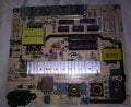
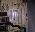
Hi, I'm trying to troubleshoot an LG 60lb5200 LCD that gets no power. I've tested the power supply outgoing pins, and get no voltage from any of them. The bottom pin reads 'EN' which I have to assume is the standby voltage.

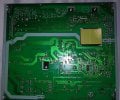
I have also tested the output of the main transformer and get no DC voltages. Does the standby voltage come out there? The fuse is good and is reading normal AC voltage across it. Can someone lead me in the right direction so I don't have to pay $100 to replace the whole board? I've included pics. Thank you!
 

Attachments

LesJones

Joined Jan 8, 2017
4,544
This will be a switch mode power supply so you would need a GOOD UNDERSTANDING of electronics to find the fault. From the way you have worded the question you have no understanding of electronics. You say "have also tested the output of the main transformer and get no DC voltages." You will never get a DC voltage out of a transformer. You also say "The fuse is good and is reading normal AC voltage across it." If the fuse is good then there should be almost no voltage across it.

Les.
 

Thread Starter

Landon6544

Joined Dec 16, 2017
2
Thanks Les! I worded the reply about the fuse incorrectly. I tested it with the continuity setting and it had minimal resistance. I also tested both sides and got expected voltage. It would be kind of hard to get voltage across it whether the fuse was good or bad. I know how a fuse works.

If you'll look at the picture, the outputs on the transformer are marked 12v, 24v, and 12v with a common ground. Now I might not have realized that there was a rectifier attached, but those are DC voltages.

It's been awhile since my Air Force electronics school. We just swapped out circuit boards in the field. I've replaced capacitors on a power supply board before, to good effect. If I had a great understanding of Power supplies and transformers, I wouldn't have had to ask for help in the first place. I know enough to not electrocute myself. It's not a steep learning curve. So, despite the condescension, you taught me something, so thank you!
 

LesJones

Joined Jan 8, 2017
4,544
If a fuse is open circuit and the load is still connected to the output side you will get a reading of almost the full supply voltage across the fuse. It was the fact that talked about a DC output from a transformer that made me doubt you electrical knowledge. The only places I can see 12 and 24 volts marked is on a connector on the right hand side of the board and on a pin of a power transistor or voltage regulator at the top of the board. The EN pin on the connector maybe an enable signal. I think you will need to see if you can find a schematic of the board on the web or trace it out yourself. I suggest that you start by reading the part number of the switching regulator control chip (The 16 pin surface mount IC on the etch side of the board.) and finding the data sheet on the web. (You will have more chance of finding this than the schematic of the board.) The data sheet will give you a good basic idea of the design of the switching power supply. The first thing I check on switching power supplies is the voltage on the main reservoir capacitors. I would expect it to be close to the peak voltage (Root 2 times the RMS voltage.) of you mains power supply. If that is not present then the fault will be between these capacitors and the mains input.

Les.
 
Thread starter Similar threads Forum Replies Date
Homebrew1964 Analog & Mixed-Signal Design 26
Similar threads
My Lamp won't light?
Top