Facebook
 Google
 GitHub
 Linkedin
Hi all,
I've lurked for a little while but am posting now because I could do with some help. Software and engine stuff I'm okay with - electronics not so much.
I was just in the middle of watching 'Whiplash' the other night when there was a decent crack/pop sound and the TV set went off - no sound, no picture, no standby light.
- I unplugged it and checked the 13A fuse in the plug with a meter (Fluke 233) which was fine.
- Took the rear cover off and had a look and a sniff. No obvious damage.
- Had a look online for the schematic (attached) to see where to begin. Found that the fuse (3.15A slow blow) immediately after the AC in had gone (F101 on the schematic, part number T3.15A H 250V 50CT VIOLET(1-LINE)).
- Stopped at this point as I didn't really know how to find out what caused the fuse to blow. A friend who knows more than me suggested it could have been just a surge so I replaced the fuse with a new one and (as expected) it popped again.
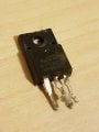
- This time, because the cover was off, I noticed a short at the MOSFET on the heat sink (Q101 on the schematic, part number mdf10n65b 650v 10a to-220fp). Sure enough there looks like a scorch mark across two of the pins. These might have been there before or I may have caused more damage by my above actions - I'm not sure.
I have scoured many forums and watched many YouTube videos to try and learn the steps I need to take to (1) narrow down the root cause of the problem and (2) eventually fix it but haven't been able to figure out the next step. One thread I read suggested de-soldering and testing all the components but common sense suggests there are better methods. Another mentioned looking for a repair kit specific to my board and just checking the components which (apparently) commonly fail. This sounds better but I couldn't find a repair kit for my board.
I know I could just buy a new power board and replace the whole thing and (hopefully) this would resolve my issue - unless the issue was somewhere else - but I thought it might be educational and fun to have a go at fixing it. Also, while we don't have a TV, the wife and I are actually having conversations! I've bought a cheap component tester (https://www.ebay.co.uk/itm/113195528307) which will come in a few days so I think I have most of the kit I need (soldering iron, basic tools, meter, etc., I already own) but I honestly lack the know-how.
If anyone is interested in helping or guiding me along to which components are likely to have failed or what to test next (and how to test it) I would be grateful.
Cheers,
Arram.
Other info - TV model LG 42LM3450, power board LGP42P-12LPB, other details in attached spec.
I've lurked for a little while but am posting now because I could do with some help. Software and engine stuff I'm okay with - electronics not so much.
I was just in the middle of watching 'Whiplash' the other night when there was a decent crack/pop sound and the TV set went off - no sound, no picture, no standby light.
- I unplugged it and checked the 13A fuse in the plug with a meter (Fluke 233) which was fine.
- Took the rear cover off and had a look and a sniff. No obvious damage.
- Had a look online for the schematic (attached) to see where to begin. Found that the fuse (3.15A slow blow) immediately after the AC in had gone (F101 on the schematic, part number T3.15A H 250V 50CT VIOLET(1-LINE)).
- Stopped at this point as I didn't really know how to find out what caused the fuse to blow. A friend who knows more than me suggested it could have been just a surge so I replaced the fuse with a new one and (as expected) it popped again.
- This time, because the cover was off, I noticed a short at the MOSFET on the heat sink (Q101 on the schematic, part number mdf10n65b 650v 10a to-220fp). Sure enough there looks like a scorch mark across two of the pins. These might have been there before or I may have caused more damage by my above actions - I'm not sure.
I have scoured many forums and watched many YouTube videos to try and learn the steps I need to take to (1) narrow down the root cause of the problem and (2) eventually fix it but haven't been able to figure out the next step. One thread I read suggested de-soldering and testing all the components but common sense suggests there are better methods. Another mentioned looking for a repair kit specific to my board and just checking the components which (apparently) commonly fail. This sounds better but I couldn't find a repair kit for my board.
I know I could just buy a new power board and replace the whole thing and (hopefully) this would resolve my issue - unless the issue was somewhere else - but I thought it might be educational and fun to have a go at fixing it. Also, while we don't have a TV, the wife and I are actually having conversations! I've bought a cheap component tester (https://www.ebay.co.uk/itm/113195528307) which will come in a few days so I think I have most of the kit I need (soldering iron, basic tools, meter, etc., I already own) but I honestly lack the know-how.
If anyone is interested in helping or guiding me along to which components are likely to have failed or what to test next (and how to test it) I would be grateful.
Cheers,
Arram.
Other info - TV model LG 42LM3450, power board LGP42P-12LPB, other details in attached spec.
Attachments
-
2.5 MB Views: 43