level shifting circuit

Audioguru again

Joined Oct 21, 2019
6,691
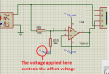
You are supposed to apply a voltage to R10 instead of connecting it to 0V. Then the opamp will raise its output offset voltage.
You also do not need to make the opamp have differential inputs using 4 resistors.
 

Attachments

Audioguru again

Joined Oct 21, 2019
6,691
You can make the resistors any value you want depending on the amount of opamp input bias current. They make an attenuator of the AC signal and of the offset voltage you add to them.
I showed equal resistor values and an input offset of +5V so that the output of the opamp can be an average DC of +2.5V and swing from 0V to +5V without damaging a microcontroller powered from +5V.
 

Thread Starter

MAINAHNOUD

Joined Jul 24, 2019
67
You can make the resistors any value you want depending on the amount of opamp input bias current. They make an attenuator of the AC signal and of the offset voltage you add to them.
I showed equal resistor values and an input offset of +5V so that the output of the opamp can be an average DC of +2.5V and swing from 0V to +5V without damaging a microcontroller powered from +5V.
So, if I put equal resistor and 5v offset voltage I get +2.5 average dc?
 

Thread Starter

MAINAHNOUD

Joined Jul 24, 2019
67
The settings on your scope are AC coupled, which would remove DC
offset when displayed on scope. You need to be DC coupled on the
scope inputs.


Regards, Dana.
Okay can you tell me from where can I adjust this setting (as a screen shot for example).
 

Audioguru again

Joined Oct 21, 2019
6,691
Your new resistors have the extremely low value of only 1k which might be a short circuit to your signal source.
Since you are biasing the input of the opamp at a positive voltage and the input of the opamp never goes negative, then you do not heed the negative supply. Connect pin 2 of the opamp to ground (0V).
 

Thread Starter

MAINAHNOUD

Joined Jul 24, 2019
67
Your new resistors have the extremely low value of only 1k which might be a short circuit to your signal source.
Since you are biasing the input of the opamp at a positive voltage and the input of the opamp never goes negative, then you do not heed the negative supply. Connect pin 2 of the opamp to ground (0V).
Yes, it work well thank you.
Finally can you tell me the calculation if I need to MN ake the signal +/-0.420v to has dc offset 0.420v to make the signal finally from 0 to 0.840 v
 

Thread Starter

MAINAHNOUD

Joined Jul 24, 2019
67
Your circuit began attenuating the signal with a differential amplifier. Now you want offset plus a gain of 2?
The triangular signal has magnitude from _0.420 to +0.420
So, I want all of this signal in positive only. So, I want dc offset equals 0.420 to make the signal finally from 0 to. 0.840.
 
Top