Lets Talk About Constant Current

panic mode

Joined Oct 10, 2011
5,307
R4 is an alternate place for load (in series with power source). it is where load would be if CC is built as 2-wire device (circuit from post #14).
just wanted to share that choice of load location affects current regulation. when testing current sources i use low value resistor. value is not critical, 1mOhm or 1 Ohm would hardly make a difference for CC designed for current in mA
 

Thread Starter

Wendy

Joined Mar 24, 2008
23,857
So I corrected the schematic and big surprise it worked! I used this layout:
CC Layout.png​

Constant current regulator#2.png​
0.5V 0ma
1.0V 0ma
1.5V 3ma
2.0V 3ma
2.5V3ma
3.0V 4ma
3.5V 4ma
4.0V 4ma
4.5V 4ma
5.0V 4ma
5.5V 4ma
6.0V 4ma
6.5V 4ma
7.0V 4ma
8.0V 4ma
9.0V 4ma
10.0V 4ma

As promised, I will be trying a different constant current regulator next.
 

Thread Starter

Wendy

Joined Mar 24, 2008
23,857
It's definitely a constant current device. I don't see any mistakes in the layout. Do you? I measured the 100 ohm resistor, it is accurate.
 

crutschow

Joined Mar 14, 2008
38,871
It's definitely a constant current device. I don't see any mistakes in the layout. Do you? I measured the 100 ohm resistor, it is accurate.
The perhaps one or both of your transistor are connected backwards, collector-emitter, as they will still work as a transistor but with very low current gain.
Double check the transistor spec sheet.

There is something definitely flaky about your circuit.
 
Last edited:

Thread Starter

Wendy

Joined Mar 24, 2008
23,857
It could be a measurement error. I was using the front panel of my power supply to get the current.
 

crutschow

Joined Mar 14, 2008
38,871
It could be a measurement error. I was using the front panel of my power supply to get the current.
So this anomaly is likely about measurement error. :rolleyes:
Why would you not use a multimeter for that measurement, since the power supply's meter is likely quite inaccurate at that low current?
 
Last edited:

schmitt trigger

Joined Jul 12, 2010
2,260
Tomorrow, the LM344 3 terminal current regulator.

Remember that the simple LM334 current regulator has a strong temperature coefficient. As a fact, it can be used as a temperature sensor.
There is a circuit on the datasheet with an additional diode and resistor which has essentially zero temperature coefficient.

Now, if you would like to test ultra-simple and reasonably good current sources, use single JFET and a single resistor.
 

kiroma

Joined Apr 30, 2014
258
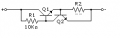
So a project like this always gnaws at me if I don't finish it successfully. I recently came across this schematic in this website. It was shown to me by other people elsewhere on AAC and on this website:

https://circuitdigest.com/tutorial/current-regulators-construction-working-and-design-types

Now I have to figure out how to program specific currents. Any ideas? R1 seems to be a constant, while R2 programs the current. Now I have to figure out how to calculate R2 to get the desired current I want.
My analysis on this circuit is that R2 must have about 0.5 V to start conducting a very low current through R1. If there's sufficient voltage across + and - (about 1 V if R1 were near 0 ohms), there will be 0.6 or 0.7 V to start Q1 conducting. If this last condition is met (in reality simulation has shown that its needed about 1.5 V), the other values are valid too.

Correct me if I'm wrong, but the total current will be somewhat near (V-0.5-0.7)/R1+0.5/R2. If there's more voltage, there's more current through the 10 kOhm resistor, so Q1 will conduct harder, and Q2 will also conduct harder trying to do negative feedback, but as these are different transistors at different base currents, they won't cancel exactly. Q1 has more gain due to being driven into the mA range, instead of the µA range as Q2. But if it's for higher powers, the loss in gain Q1 will present will win the battle against Q2 gain. So the current can drop (as the voltage increases), I think.

Here's the LTspice sim of the post #14 circuit:
It's not a great constant-circuit circuit, but it's simple and gives adequate performance for many applications, such as for a current-limiter.
You test results with the real circuit should be similar.

It should be noted that constant-current circuits used for current limiting are often simpler with poorer performance than those used to generate a constant-current through a varying load resistance.
And any discussion of constant-current sources should include the Howland current-pump which is a single op amp circuit that can generate a bidirectional output.

View attachment 371779
I think that your simulation reached the "saturation" of what can be given to R2 in terms of current by Q1 with a 10 kOhm R1. R1 limits too much, with 5 V you have about 3.8 V left, which is about 0.38 mA for Q1 to amplify, and remember Q2 is acting the other way around.
ie. R1=10 kOhm is for very low currents.
I can be wrong, though, because I haven't simulated anything yet, I don't have much time today.
 

Thread Starter

Wendy

Joined Mar 24, 2008
23,857
So I tried the LM334. It is a total flop. At this point I'm wondering if it is a counterfeit. Pictures to follow.
 

Thread Starter

Wendy

Joined Mar 24, 2008
23,857
Click the picture to enlarge.
This is the parts bag.
20261001_193331.jpg
This is the part.
20261001_204808.jpg
And this is the circuit it was put in.
20261001_203040.jpg
I have ordered these parts twice from Amazon, I just need to get one good part to know that these are counterfeit. If anyone knows where I can get them, let me know.I will probably sent the last order back as faulty.

I'm going back to the first design since I can't seem to get this one to work.
 
Last edited:
Top