LEDs switch circuit build help

Thread Starter

Peter Trinh

Joined Jan 29, 2018
26
Hi all

I was hoping someone on here could help me advise me of a little project my wifes given me.

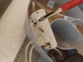
Shes purchased 5x these kids letters which have small led bulbs in them powered by 3x1.5v button coin cell ag13 batteries it comes with a on/off switch at the back. (https://www.matalan.co.uk/product/detail/s2643130/kids-alphabet-led-light)

Now what she wants me to do is find a way to connect them all to one switch so with a press of a button all 5 letters will light up (instead of flicking 5 switches on the back of each letter) thanks guys.
 

Reloadron

Joined Jan 15, 2015
7,517
Without seeing the actual circuits and switch configurations my guess would be to place a single On/Off switch across the other 5 switches in parallel. Tie all of the switches together in parallel.

Ron
 

Bernard

Joined Aug 7, 2008
5,784
Are the letters going to be attached to a backing or strung together with wires ?
How about using a AC adapter, battery life might be short.
Wire all letters in parallel with a switch in one lead. Adapter will then be a parasitic load when not in use. Letter LEDs are probably in parallel, we'll just have to grit our teeth & close our eyes & reduce supply voltage as much as possible.
 

AnalogKid

Joined Aug 1, 2013
11,042
Last November I did something similar with some small LED Christmas trees. How are you at soldering a wire onto a small metal tab inside a plastic box without melting the plastic?

The three batteries are in series. One long-term approach is:

Use a volt meter to determine the + and - ends of the overall battery string.
Remove the batteries and solder red and black wires to the + and - battery contacts.
Get a 5 V wall wart; cut the connector off the end
Solder a 1N4004 diode in series with the + end to drop the output voltage a little
The diode connects to one switch terminal
The five red wires connect to the other switch terminal.
All black wires go to the power supply - lead.

This puts all five LED strings in direct parallel, something that can cause brightness problems if the letters do not have an internal current limiting resistor acting as a ballast. If so, plan B is to wire the power supply + lead to the switch, attach five diodes to the other side of the switch, and have one diode go to each letter. The dynamic impedance of the diode should help even out the letter brightness's.

ak
 

Thread Starter

Peter Trinh

Joined Jan 29, 2018
26
Thanks guys,

Im a complete newbie at this, done some soldering in the past but nothing that includes working out currents and volts. I guess first thing i i should do is open the back and check for resistors and post the photo for you guys,

I would prefer to run it on a battery instead of mains supply, is there a way to run them with the batteries supplied? Or discard them for a few bigger ones?
 

BobTPH

Joined Jun 5, 2013
8,958
Yes, take the batteries out, get a 3 AAA or AA holder. Wire the negative of the battery pack to the negative of all 5 letters. Wire the positive to a switch, and the other side of the switch to all of the positives of the 3 letters. You can probably even get the battery pack with a built in switch (look on EBay.)

However, you do still have to make sure there is resistor in the circuit. I think it is 50:50 that there is not and they are relying on the internal resistance of the batteries to prevent the LEDs from burning out. If there is no resistor, you will have to add one in series with each of the 5 letters.

Bob
 

Thread Starter

Peter Trinh

Joined Jan 29, 2018
26
Thanks Bob i'll check for resistors after work, how would i know what resistor is correct for the led lights? And would 3xAAA be enough to power all letters? Any recommendations on wore types i should use? Thanks

Peter
 

BobTPH

Joined Jun 5, 2013
8,958
3 AAA will power the 5 of them longer than the button cells would power one.

Any type of insulated wire is okay.

Something like a thin speaker wire would be fine.

Bob
 

Reloadron

Joined Jan 15, 2015
7,517
Hi Bob

Well i've opened the back cover and im sure i can see a resistor i attached it below not sure if its up loaded, but would this resistor need to be changed?
Nope. Leave the existing resistor(s). I would anyway. They used a single resistor in series with the LEDs which look to be in parallel, considering a button cell battery they must be in parallel.

Ron
 

Thread Starter

Peter Trinh

Joined Jan 29, 2018
26
Thanks

So when i re-connect the resistor does one end be soldered to the - and the other + like how they did it? Or which end should the resistor be connected too?
 

Reloadron

Joined Jan 15, 2015
7,517
It looks like they are switching at the battery. They look to come off the battery with what looks to be a 15 Ohm resistor and then feed the LEDs which look to be in parallel. What you could likely do and in the interest of simple is remove all of the batteries and solder to the existing battery terminals placing all the letters in parallel. Then add a switch in series with your new battery configuration. Just leave all the existing switches ON and place all the letter battery terminals in parallel. Make sense?

Ron
 

Thread Starter

Peter Trinh

Joined Jan 29, 2018
26
Hi Ron

I think i understand so solder all the letters in parallel, one letter to the next letter then the last one solders to the new switch and battery? Is that correct? What sort of switch can i use? Whats thr minimum voltage?
 

Reloadron

Joined Jan 15, 2015
7,517
Just about any switch will work for this application. You are only switching about 1.5 volt and well under an amp. It would be by name a SPST (Single Pole Single Throw) switch. The exact switch design is more a matter of decor as to what you like or may have laying around. Yes you would solder all the + and - battery terminals in parallel so all the + are connected together and all the - are connected together. This way we don't remove all the existing little switches and just leave them in the On position. Your new battery - goes to all the other - and your new battery + in series with the added switch which then goes to all of the other battery +.

Ron
 

Thread Starter

Peter Trinh

Joined Jan 29, 2018
26
If im using 3xaa batteries that makes it 4.5v would i need a switch for that amount for volts? Also if one letter is using 3x13ag button coin cell 1.5v each, would 3xaa be enough for 5 letters maybe 4xaa or more? How do you calculate this?

Thanks
 

Reloadron

Joined Jan 15, 2015
7,517
I believe the coin cells you had in the letters were 1.5 volt so you would want 3 AA batteries in parallel. Batteries in series the voltage is added so 3 AA in series would be 3 * 1.5 = 4.5, not what you want. 3 AA in parallel would be 1.5 volts but offer more current for the longer run time. Let me make a little drawing and post it.

Ron
 
Top