Facebook
 Google
 GitHub
 Linkedin
I apologize if I am posting this in the wrong section.
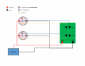
I have a 12v project I am working on, which has 2 momentary 1NO1NC switches with build in Led's(these to be exact (https://tinyurl.com/yytmp2qs)
I can wire them so that the led lights up when the button is pressed, that's simple enough. What I am wondering, is there a way to wire it so that if one is pressed, it not only turns its led on, but also turns the other one off?
So basically, if I push "button 1" it lights up, if I then push "button 2" it lights up, but also turns off "button 1's" light, and so on.