Facebook
 Google
 GitHub
 Linkedin
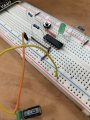
Here is a generic circuit using a Set-Reset flip-flop such as CD4013.
Note that the SET and RESET inputs are ACTIVE-HIGH, i.e. they require logic HIGH to activate the function.
The D and CLOCK inputs are not required and are wired to GND.
The output can come from Q or /Q.
If you want to use Q then the LED D1 and resistor R1 are connected to GND instead of VDD.

Note that the SET and RESET inputs are ACTIVE-HIGH, i.e. they require logic HIGH to activate the function.
The D and CLOCK inputs are not required and are wired to GND.
The output can come from Q or /Q.
If you want to use Q then the LED D1 and resistor R1 are connected to GND instead of VDD.