One would assume ( - dangerous, I know - ) that at 12 volts and 290mA there should be a current limiting resistor built in at a value of 41.38Ω (calculated). At 14.5V, which is absolutely possible, at 290mA there should be a current limiting resistor built in at a value of 50Ω.
You are making the classic mistake of throwing any voltage and any current at Ohm's Law and thinking the resulting number means something.
To get 41.38 Ω, you are assuming that the full 12 V appears across the resistor, which means that the LEDs themselves have zero voltage drop across them.
These are chip-on-board and it looks like there are 28 LEDs on a strip. The COB almost certainly incorporates the resistors the same way. Without tearing one of them apart, there's no way to know about the series/parallel configuration that might be at play. It's unlikely that they are all in parallel as that would waste a lot of power. More likely there are seven strings of four in series. The more that there are in series, the less the overhead voltage, which means that they become more sensitive to changes in supply voltage.
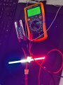
Here is the current measurement for a single LED light.
The second photo is the entire light rig.
1st LED line uses four long light strips and 4 square diode lights. The four long light strips are dead.
2nd LED line uses two long light strips and two wire lights. The two long light strips are dead too.
Measure the voltage of your 11.1 V battery with the LED strip connected.
Measure the current (already done): 170 mA
Then repeat these measurements connected to your truck battery (engine not running).
Then (with the LEDs disconnected so that you don't destroy them), measure the battery voltage of your truck with the engine running (wait a few minutes to let the battery recharge after starting it).
This will let us estimate the value of the current limiting resistor being used, which will let us estimate the current that might be flowing when the engine is running and the alternator is putting out a higher voltage.
IF you have extra LED strips that you are willing to sacrifice for testing purposes, repeat the above measurement with the engine running.
To get 41.38 Ω, you are assuming that the full 12 V appears across the resistor, which means that the LEDs themselves have zero voltage drop across them.
Well, nobody's perfect. Then again I AM a "Classic".
I guess we need to know the Vf of the diode pack. IF (big "IF" there) IF the Vf is 9V (as an example) then that leaves 3 to 4.5 volts to be dropped by the resistor. New calculations suggest 10.3 to 15.5Ω.
Well, nobody's perfect. Then again I AM a "Classic".
I guess we need to know the Vf of the diode pack. IF (big "IF" there) IF the Vf is 9V (as an example) then that leaves 3 to 4.5 volts to be dropped by the resistor. New calculations suggest 10.3 to 15.5Ω.
Wait a minute - - - you're testing these with a 11.1 volt battery? And after that you expect them to work in a 12V system where 12V is nominal, 13.6 to 13.8V is operational and max charge can be as high as 15V? IF you're seeing 15V after starting the engine (is normal) you're 50% OVER the rated voltage and 73% over your battery voltage. No wonder why they're blowing out the moment you start the engine.
The specs say 290mA. I'm assuming they mean at 12 volts.
OK, the proper solution would be to add in a ballast resistor. And since I screwed up the numbers before I'm not even going to try.
According to these numbers and assuming the 11.1V battery is a constant voltage, the load would be 65.3Ω. So at 13.8V with a 65.3Ω load the current draw would be 211mA. The more I think about this the more I'm confused.
Yes, he sanity-checked them with a (nominally) 11.1 V battery. This likely explains why he only saw 170 mA instead of something closer to 290 mA.
Since these are, supposedly, designed for automotive use, they should have been designed to accommodate the full range of voltages seen in a 12 V automotive system.
The evidence suggests they weren't. Given the price and the source, that isn't that surprising.
The question now is whether enough after-the-fact magic can be thrown at them to get something that works (well enough).
Which is why he is taking the additional requested measurements.
Which we have to back into the Vf indirectly by trying to get a couple of different operating point values of the strips in order to, at least approximately, estimate the value of the current limiting resistor (assuming there is one -- which is likely). Once we have that, we can assume that the Vf at both operating points is roughly the same and solve for what it is.
Measure the voltage of your 11.1 V battery with the LED strip connected.
Measure the current (already done): 170 mA
Then repeat these measurements connected to your truck battery (engine not running).
Then (with the LEDs disconnected so that you don't destroy them), measure the battery voltage of your truck with the engine running (wait a few minutes to let the battery recharge after starting it).
This will let us estimate the value of the current limiting resistor being used, which will let us estimate the current that might be flowing when the engine is running and the alternator is putting out a higher voltage.
IF you have extra LED strips that you are willing to sacrifice for testing purposes, repeat the above measurement with the engine running.
These arrays are very common and sold as "12V" arrays, as others have realised, they are wired as multiple parallel strings of 4 chips in series. There are many such arrays in all sizes and shapes.
The sellers of these generally have no clue how you drive LEDs, they just think that with 4 x 3V chips in series that you can connect them to 12V. As also stated, their current response is extremely non-linear with respect to voltage, like all component LEDs they must be driven with a constant current source.
The simplest way is actually a constant current IC, there are many such ICs made for automotive use, like the NSI series from Onsemi (available at Mouser etc), they are extremely simple to use, they are just treated as a smart resistor, although they need up to 3V of overhead.
However, there is a better option in the AMC7140 which is an adjustable linear driver with very low voltage overhead requirement. While the AMC7140 is generally not available, there are two electrically and mechanically identical chips, the MaxLinear XR46004 and Taiwan Semi TS19601, also both available from Mouser. These work fantastically well, I use them in my products and they are pretty much bulletproof provided you give them adequate heatsinking.
I would not be messing with voltage regulators, that's not how you drive LED arrays, use current regulation like you should be.
Ok, further to my post, neither the MaxLinear XR46004 or Taiwan Semi TS19601 are available from mouser any longer, I bought some a year ago and they had quite a few thousand. Checked them on the Digikey site and they are both listed as no longer manufactured, which is pretty sad because they are the best design of their type that I've found. However, Digikey have some TS19601 in stock, so they are available at the moment.
Did you ever measure the actual voltage of that LiPo battery? If not, please do (assuming you haven't charged or used it much since you took that current measurement).
The two data points we have are: 150 mA @ 12.75 V and 780 mA @ 14.72 V.
That large an increase with just a 2 V change in voltage leads me to suspect that there is no current limiting resistor and they are relying primarily on the resistive behavior of many LEDs (which makes it a very bad design, especially for an automotive application).
I'm guessing that the nominal forward voltage of the LEDs in this thing is 3.0 V (or something close) and they have four in series giving a nominal Vf per string of 12 V. That means that each LED is nominally carrying about 40 mA of current (if operating at the total current of 290 mA in the data sheet).
If your LiPo battery was really at 11.1 V, I'm surprised you got much current at all -- and getting 170 mA (i.e., a bit more current that at 12.75 V) is very strange, so I suspect your LiPo voltage is at somewhat higher.
Was it the exact same LED strip that you used with both batteries? The difference from one strip to another could easily count for the difference in results.
The best way to drive these is with a current driver. LED strings have become so common that there are a lot of very cheap options out there. I don't work with them much, so I'm not familiar with what's actually available. I know you are looking for a module rather than building something yourself. It's also apparent that you want to use ultra-cheap components, which is going to make it a lot harder to do it right.
Because there is no overhead voltage available at the intended operating voltage, using two or three series diodes may not work well. But it might be worth a try and it is easy to do, particularly as a test.
You might try putting a resistor in series with the LED strip that is about 10 Ω (somewhere between 6.8 Ω and 15 Ω). But you're going to need 2 W resistors. That should protect the string from burning out when the engine is running, but there are some caveats here. First, the value that works for one strip might not work well for the next. Second, since these are on the outside of a car, the temperature variation is going to be pretty extreme and that is going to impact the behavior, possibly so much that it will be very noticeable and annoying. But, if not, then life is good. If it is, then you can always revisit and seek a better solution (such as a proper current driver).
 Facebook
 Google
 GitHub
 Linkedin