 Facebook
 Google
 GitHub
 Linkedin
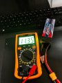
Here it isDid you ever measure the actual voltage of that LiPo battery? If not, please do (assuming you haven't charged or used it much since you took that current measurement).
The two data points we have are: 150 mA @ 12.75 V and 780 mA @ 14.72 V.
That large an increase with just a 2 V change in voltage leads me to suspect that there is no current limiting resistor and they are relying primarily on the resistive behavior of many LEDs (which makes it a very bad design, especially for an automotive application).
I'm guessing that the nominal forward voltage of the LEDs in this thing is 3.0 V (or something close) and they have four in series giving a nominal Vf per string of 12 V. That means that each LED is nominally carrying about 40 mA of current (if operating at the total current of 290 mA in the data sheet).
If your LiPo battery was really at 11.1 V, I'm surprised you got much current at all -- and getting 170 mA (i.e., a bit more current that at 12.75 V) is very strange, so I suspect your LiPo voltage is at somewhat higher.
Was it the exact same LED strip that you used with both batteries? The difference from one strip to another could easily count for the difference in results.
The best way to drive these is with a current driver. LED strings have become so common that there are a lot of very cheap options out there. I don't work with them much, so I'm not familiar with what's actually available. I know you are looking for a module rather than building something yourself. It's also apparent that you want to use ultra-cheap components, which is going to make it a lot harder to do it right.
Because there is no overhead voltage available at the intended operating voltage, using two or three series diodes may not work well. But it might be worth a try and it is easy to do, particularly as a test.
You might try putting a resistor in series with the LED strip that is about 10 Ω (somewhere between 6.8 Ω and 15 Ω). But you're going to need 2 W resistors. That should protect the string from burning out when the engine is running, but there are some caveats here. First, the value that works for one strip might not work well for the next. Second, since these are on the outside of a car, the temperature variation is going to be pretty extreme and that is going to impact the behavior, possibly so much that it will be very noticeable and annoying. But, if not, then life is good. If it is, then you can always revisit and seek a better solution (such as a proper current driver).
Attachments
-
 1.9 MB Views: 13


