LED Light Power Supply

AlbertHall

Joined Jun 4, 2014
12,625
If the two blue topped things are transformers, which I believe they are, then the answer must be no as the transformer ratios would need to be changed.
 

Thread Starter

tofino

Joined Feb 18, 2011
13
If the two blue topped things are transformers, which I believe they are, then the answer must be no as the transformer ratios would need to be changed.
Indeed they are transformers to me. The one close to the big capacity reads RH 15 and the other RH 21. Can they be changed to do the job. Is there any other feasible way of making the light to work apart from using a step up 110-200v transformer. Its a pity because the light comes with a RF remote for on/off, ambiance control. Thanks.
 

Dodgydave

Joined Jun 22, 2012
11,395
I would say its a switchmode psu, mains input on the right side via Yellow capacitor and four diodes for bridge rectifier, looks like there are a couple of resistors next to the mains chip 330K, can you take a picture of the chip to see what markings are on it, then check the datasheet.??
 
Last edited:

dendad

Joined Feb 20, 2016
4,637
You could change the input rectifier circuit, make it a voltage doubler instead of just a rectifier. But if you don't know what that is, do not proceed as you do not have the knowledge to safely modify what will be connected to the mains.
Get the correct power supplies. that will be a lot wiser.
 

Thread Starter

tofino

Joined Feb 18, 2011
13
Thanks for the replies. The yellow capacity is 0.1 uf, the four diodes are S2M LJ. The transistor next to the blue cap is 13001 S8D (please see date sheet). I can't find any markings on the 8 leg chip.

I have undergone a couple of basic electronic courses which taught me how to use a multimeter to test components, and soldering skill as well. I was also taught on how to make minor repairs to microwaves, refrigerators etc. Last but not least, on safety precautions on handling AC/DC electricity.

Thanks again for any assistance/advice.
 

Attachments

dendad

Joined Feb 20, 2016
4,637
This circuit shows the rectifier circuit to manually switch between 120V and 240V in.
So if you make the power rectifier a voltage doubler, you will not have to alter the rest of the power supply.
PowerRectifier.jpg
A lot of the older PC supplied were like this, and had a voltage selector slide switch or a movable link.
So for a fixed voltage doubler, the 2 diodes connected to the switch are not needed, and the mains wire is hard wired to the center of the 2 electros.
Use 3A diodes too so they can handle the switch on surge. It would be a good idea to add a slow blow fuse in the mains wiring.
Make both capacitors the same value, and for the lower power of your supplies, you could probable get away with a couple of 47uF 220V caps. The 100K resistors are for safe discharge and voltage balancing. This rectifier circuit may be built in an external box and the resultant "240V" (about 340VDC) volts fed into the mains input of the power supplies.
BUT BE CAREFUL!!!!!
 
Last edited:

Thread Starter

tofino

Joined Feb 18, 2011
13
Thanks for the circuit and detailed explanation. This has enriched my knowledge a lot. Not so much as a question, if it is about voltage doubling, can I use a commercial small voltage adapter AC110 to 220V to do the job. In such a case, how many A the adapter needs to be as it is expected to be on 24 hours a day.

Lastly, is it complicate to alter the original power supply making it to work on 110V.
 

dendad

Joined Feb 20, 2016
4,637
Lastly, is it complicate to alter the original power supply making it to work on 110V.
Yes, it is pretty major mod to change the power, so a voltage doubler will be easiest as a mod. That way you don't have to fiddle with the switchmode circuitry at all. This mod will supply the DC volts it is designed to run on anyway. But if they are designed for dimming, and you want to use that, go with the transformer.
An external 120V to 240V transformer will work well. Have a look at the max power rating of the LED power supplies and get a transformer half again bigger I reckon if you go that way.
 

Dodgydave

Joined Jun 22, 2012
11,395
This is what i think you have circuit wise. The Yellow cap is being used as a voltage dropper with the two 330K (334) resistors to the bridge rectifier to drop the voltage across the smoothing capacitor C1, Can you measure the voltage across it,,

this is feeding the two chips U1,2 which are the led outputs, ideally you need to get the markings on these, look at the datasheet for pin supply, and measure them to see how low they are, it will be just a matter of reducing the two 330K resistors or increasing the value of the Yellow capacitor.


(transformerless LEDs directly to the mains circuit not permitted by the User Agreement removed by moderator.)
 
Last edited by a moderator:

AlbertHall

Joined Jun 4, 2014
12,625
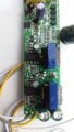
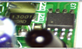
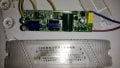
I purchased a LED ceiling light with a power supply of AC175-265V. (please see photo). It does not work with my home supply in Canada which is 110V. Can I modify it to work, eg changing resistors etc. Thanks.
Does this unit use an IR remote control?
 

Thread Starter

tofino

Joined Feb 18, 2011
13
Thanks again for the replies.

(1) An external 120V to 240V transformer is indeed a good choice. The cover of the LED light power supply reads:
Power: 37W-50W x2
Pri : AC 175-265V 50/60 Hz
Sec : 260MA +- 5%.
So what size of the transformer should I look for in terms of A or Watt,

(2) As I have two of these lights, I would like to venture the challenging way also, along this brush up on my soldering skill. The reading of C1 capacitor and U1, 2 are attached. U1 controls the white leds while U2 the yellow ones. I cannot find the data sheet by googling the markings on U1 and U2. Perhaps they have another parts name. If so, what are they.

(3) The unit comes with an IR remote.

CaptureU1.PNG CaptureU2.PNG b0ard reading.jpg adapter size.jpg
 

AlbertHall

Joined Jun 4, 2014
12,625
(3) The unit comes with an IR remote.
In that case, I believe that board has two separate power supplies derived from the mains.
1. A low power transformerless supply for the remote function fed by the yellow capacitor.
2. A higher power supply - a bridge rectifier from the mains feeding the large capacitor. This supply feeds the circuitry around the two transformers for the lights. This supply is only switched on when required by the remote control so the standby power consumption is low.

Given this, the step up transformer on the input would be a good solution.
 

Thread Starter

tofino

Joined Feb 18, 2011
13
In that case, I believe that board has two separate power supplies derived from the mains.
1. A low power transformerless supply for the remote function fed by the yellow capacitor.
2. A higher power supply - a bridge rectifier from the mains feeding the large capacitor. This supply feeds the circuitry around the two transformers for the lights. This supply is only switched on when required by the remote control so the standby power consumption is low.

Given this, the step up transformer on the input would be a good solution.
Can you advise me the size of the step up transformer in terms of A or Watt. Thanks.adapter size.jpg
 

Thread Starter

tofino

Joined Feb 18, 2011
13
I purchased another led ceiling light (please see photo). Spec is 100V 50/60 HZ 65W. I want to use it in a place where mains supply is 220V.
My questions are (1) Is it easy to make alterations to the circuit to make this happen.
(2) If a step down transformer is to be used. What watt should it be, now that the voltage is 220V.

Thanks.
 

Attachments

dendad

Joined Feb 20, 2016
4,637
Use a 100W 220V to 100V step down transformer with isolation. Not an auto transformer!
I don't think modding the light is doable, at least, not easily.
 

Thread Starter

tofino

Joined Feb 18, 2011
13
Use a 100W 220V to 100V step down transformer with isolation. Not an auto transformer!
I don't think modding the light is doable, at least, not easily.
Just one more question, can I connect the ac power input of two of these lights in series to make it to 200V. Thanks a lot.

Lastly, I was thinking of replacing the whole control board with something like quoted in #1 and #2 of this thread but hated to do this as the original one looked to be of much higher quality.
 

dendad

Joined Feb 20, 2016
4,637
Just one more question, can I connect the ac power input of two of these lights in series to make it to 200V.
No. I would not. You cannot be sure the current will be the same at any time so you will pop one then the other as the voltage will not divide equally. They are not plain resistors.

Just go with an isolation step down transformer as you cannot rely on the isolation from mains to chassis being the same standard for a 220V as a 110V one, especially if this is a Cheap China version.
Or else, buy a new light. When mucking around with the mains, safety first and last!
 
Top