Power Supply for LED light configuration

Thread Starter

jrb4281

Joined Nov 5, 2017
6
Hello,

I am trying to make a LED light configuration. I have bought 1W, 350mA LEDs. These are the VF for the following colors:
Red 2.0-2.2V
Infrared 2.0-2.2V
Yellow 2.0-2.2V
Natural White 3.0-3.4V
Blue 3.0-3.4V
Ultraviolet 3.0-3.4V
Green 3.0-3.4V
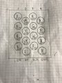
I want to do 3 separate light configurations all three identical. 16 LEDs per configuration. Most likely going to go with 1 of every color, except 5 red and 5 blue. I am trying to determine the power supply to use that I can hopefully run all three configurations from in parallel with the 16 LEDs per configuration in series. I know that meanwell makes a combination power supply and driver for LEDs now and didn't know what size to get. If my math is correct, it would be a total of 48W for all the LEDs together and roughly 160V (I based this on 3.4V times the 48 LEDs knowing that that gives me some room for fluctiations). Please let me know what size driver V, A, and W so that I can properly power my lights and show me the math that draws to your conclusion so that I can understand in case I want to change the combination of colors.
 

ScottWang

Joined Aug 23, 2012
7,501
Please upload the schematic as 800x600 gif or jpg file, and label the voltage and color of LEDs, using the schematic is more easier to understand what you want to do and the members have the same target .
 

Thread Starter

jrb4281

Joined Nov 5, 2017
6
This is what I'm thinking for the initial configuration of one set. I would parallel three of these to one power source. The lights may change depending on the necessity of the plants in my aquaponics system.
 

Attachments

BobTPH

Joined Jun 5, 2013
11,522
You cannot parallel separate strings on a constant current driver, this defeats the purpose as they will not share equally.

If you have 3 strings of 16 LED, you will need 3 drivers, each supplying 350mA (or less for better life) and a voltage ranges that includes the sum of the forward voltages of all 16 LEDs.

Bob
 

dl324

Joined Mar 30, 2015
18,333
If my math is correct, it would be a total of 48W for all the LEDs together and roughly 160V (I based this on 3.4V times the 48 LEDs knowing that that gives me some room for fluctiations).
Assuming the 1W, 350mA numbers are meaningful, your math is a little short of reality. You have 48 nominally 1W LEDs, but you're not allowing for power dissipation in whatever circuitry ends up providing the current.

First off, consider the red LED which has a 2.0-2.2V forward voltage spec. If you calculate the current from the power specification, you get P = IV -> I = P/V = 1W / 2.2V = 450mA (approximately). If you use 2V for the forward voltage, you need half an amp to get 1W. So either the power rating or the current rating are suspect.

If you wire the 48 LEDs in series and use a 160V supply, there will be some dangerous voltages that you'd need to deal with.

A more reasonable approach might be to arrange them in series and parallel to lower the required supply voltage. Depending on your objectives, you could use simple current limiting resistors or use current sources.
 

philba

Joined Aug 17, 2017
959
Can you post the data sheet for these LEDs? As several people pointed out, the Vfs, currents (Ifs) and wattages you posted are inconsistent. I'd guess that Vf and If are more likely to be accurate but a real datasheet will help sorting that out.

Assuming the Vf and If are correct, then compute the wattage. What you will find is even the red or yellow LEDs which appear to be "only" 700 mW devices will need some serious heat sinks.Your datasheet will give you what you need to understand how hot each one will get. That will in turn help you to determine the heat sink requirements.

I agree with Dennis, serial/parallel to decrease the total voltage. Watch the resistors' wattages if you go that way - they'll get hot too.
 

Thread Starter

jrb4281

Joined Nov 5, 2017
6
This is all that was given to me from the manufacturers. I hope it has the information you're looking for. My guess is that the Wattage would be incorrect.

When you say arrange them in series and parallel to lower the required voltage supply, what would I put in series and what would I parallel. Also, I only have a very basic understanding of circuits and do not know much about current limiting resistors or current sources, could you elaborate on how I could implement them in this case?
 

Attachments

dl324

Joined Mar 30, 2015
18,333
This is a series parallel combination from another current thread:
upload_2017-11-6_11-46-54.png

This shows 35 LEDs, but the concept is the same.

One way to approach this is to pick a convenient power source voltage. Since you won't be operating from batteries, you have more options: 12V, 18V, 24V, ...

Laptop chargers are typically around 18V@2+ amps and are readily available at second hand stores for $5-10.

Once you decide on a supply voltage, it's just a matter of arithmetic. Sum up the forward voltages of each string of 4 LEDs (use the max voltage specified for each). The supply voltage you choose needs to be greater than the highest voltage string, with some headroom for a current limiting resistor.

Once you know the supply voltage and the voltage of each string of series LEDs, you can use your desired current to determine the value for the current limiting resistor.

You can increase or decrease the number of series LEDs, but the objective is to minimize power dissipation in the resistors because that isn't useful for your application.
 

philba

Joined Aug 17, 2017
959
I agree that laptop power supplies are a good choice. For some reason I don't quite understand, they are often 19V.

To take dennis' explanation farther, once you have figured out your strings you subtract the totaled up Vfs from the power supply voltage to get the "left over" voltage. Then, using the desired current and left over voltage you can figure out the resistor value. Then with that you can figure out the the wattage of the resistor.

Example: 5 white LEDs in a string is 3.4 * 5 or 17 Volts. With a 19V supply, you have 19-17 = 2V to deal with. Ohms law is V=I*R. (I is current) Rearranging it you get R = V/I = 2V/.350A = 5.71 ohms. Pick the next size larger standard value, say 6 ohms. To compute wattage, you multiply current times voltage = V*I = 2*.35 = .7 watts. Resistors tend to come in 1 and 2 watt sizes. I would get the 2 W one, 1 watt is cutting it too close.

Now, You will need to think about how you are going to mount the LEDs. They are going to get hot, very hot, and you will need a way to get rid of the heat before it destroys them. Unfortunately, no data sheet means that you are going to have to take a guess at what might work. I would start with some sort of metal plate to mount them on.
 

Thread Starter

jrb4281

Joined Nov 5, 2017
6
Ok, so I did some math and here is what I have come up with. I will need to get a 18V power source and 3 different resistors.
I will have 12 strings in total, 4 per light set. Two strings have the matching fV of 12.4. When you take that away from the 18V supply 5.6V are left over. Divide that by .35A and I will need 16 Ohms, and then 5.6V times .35A gives me 1.96W. So for this string I would need a 17 Ohm 3W resistor? Then the other two strings you can see my math in the image. For the one that is 10V string I would need a 23 Ohm 4W resistor, and the 11.2V string would need a 20 Ohm 4W resistor? Please check my math. Also, I plan to mount each set of 16 lights (4 strings) to its own heat sink with the following fan attached. Do you think this will be sufficient? And will an 18V supply still be enough to run the 48 lights and 3 of these fans? I just got it off amazon and was going to strip the wires and parallel them into the circuit.

Thanks!!
 

Attachments

ScottWang

Joined Aug 23, 2012
7,501
Considering the usage life of led, when you using them with light up and not flashing then you need to only counting 80% of rated current, and all your calculation about the Vf should be count on Vmax of rated voltage, like the blue led rated voltages as 3.0-3.4V/350mA then you need to count it as 3.4V or you can measure it when it drawing 280mA(80%) and to see how much volts of Vf.
 

philba

Joined Aug 17, 2017
959
You math looks ok to me. Several points, though.
  • You need to add up all the current (12 * .35A) to get total current draw. You power supply should be rated around 50% more than that. Running your supply at 100% of rated capacity is a problem in the making. Based on your numbers, you need a 6 Amp PS.
  • You can decrease the power supply needs by putting more LEDs per string (and thus decreasing the number of strings). Your first string with the 12.4V Vf could have another LED on it. Your Vf would be 15.5 and you'd have 2.5V for the resistor. You'd have 3 strings of 5 plus one to put on some other string. It's ok to mix as long as the current is the same. Smaller voltage drop means lower wattage resistors.
  • Finding power resistors in the right wattage and resistance is kind of hit or miss. So don't be surprised if you need to rejigger your strings.
  • Scott has a good point about measuring the Vf under actual usage. Especially since you don't have a data sheet.
 

Thread Starter

jrb4281

Joined Nov 5, 2017
6
So, I redid my math based on the 80% of the max fV and the total amperage of the circuit. Does this look a little more reasonable for what I can buy?

Also, regarding the fan, can I do the same thing where I add resistors in front of the fan so that it is possible to run a 12V fan on a 18V power supply?

Thanks
 

Attachments

ScottWang

Joined Aug 23, 2012
7,501
If the 12v fan is like the fan used in computer then you can calculate the watts for resistor as W=V*I, and choosing the real wattage equal to watts * 3 of the calculation values, if the rated current of fan is 0.2A then it could be draw 0.1A is enough to drive it, so you can also using a 6.2V zener diode to instead of the resistor, you also need to calculate the watts for the zener diode.
 

dl324

Joined Mar 30, 2015
18,333
can I do the same thing where I add resistors in front of the fan so that it is possible to run a 12V fan on a 18V power supply?
You can use this circuit with a power transistor to reduce the voltage for all three fans:
upload_2017-11-7_9-18-47.png
You would omit the capacitor and regulator. This was taken from a Nat Semi Voltage Regulator Handbook.

The zener can be a typical half watt. R depends on the zener current you choose. Zener voltage should be about 1V lower than the drop you want due to the BE voltage.
 

philba

Joined Aug 17, 2017
959
Yeah, the easiest way to go is the LM7812. The data sheet has the circuit diagram.

On your wattage calcs - you really need to move up to 2 watt resistors. 1 Watt resistors will get super hot. The good news is I found 13 ohm 2 watt resistors. Vetco electronics appears to have them. No indication of in stock or not, though. Probably others do but I was shocked to find them at all. 5 ohm should be easy to find.
 

Thread Starter

jrb4281

Joined Nov 5, 2017
6
I have successfully gotten the lights to work and followed the suggestions of improving the wattage of the resistors. As I do the final mounting of the lights on a heat sink, I am having trouble understanding the LM7812. I looked up the data sheets and it seems that there are multiple versions of the LM7812. How do I know which one to choose, and do I need one per fan?
 
Top