LED light panel in fridge

Thread Starter

robismod

Joined Sep 22, 2015
449
If you replaced the LED strips but didn't replace the power supply board and still had the identical problem, it's either:

● The power supply board, with the most likely problem being the electrolytic capacitors as I stated in post number 2.*

Or

● Bad cables between the LED strips and the power supply board, an unlikely failure.

* The argument that it can't be the power supply because one side flashed and one side doesn't assumes that the power supply is connected in parallel to both strips. Looking at the board however suggests there may be separate sections for each strip.
Thanks Jon…late last night I piddled with it more. Remember, the new unit (module with two LED panels) acted the same way and on the same side. I kept fiddling with the 4 wire connector that couples to the new module, and I would almost swear it’s an erratic connection on one of the 120v wires feeding the new module. I could make it stay lit steady for a bit and my last attempt for the night it was still working fine. Couple times when I opened the doors that same LED panel slightly flickered and then stayed lit…
More tomorrow…
 

Thread Starter

robismod

Joined Sep 22, 2015
449
If you replaced the LED strips but didn't replace the power supply board and still had the identical problem, it's either:

● The power supply board, with the most likely problem being the electrolytic capacitors as I stated in post number 2.*

Or

● Bad cables between the LED strips and the power supply board, an unlikely failure.

* The argument that it can't be the power supply because one side flashed and one side doesn't assumes that the power supply is connected in parallel to both strips. Looking at the board however suggests there may be separate sections for each strip.
One more thing from last night…
I was running some DC to the LED panels to see if they were still lighting ok (I had separated them from the module.) My wall wart supply was 12v but I believe it was putting out more like 16-17v…I would briefly touch the input power pads and the lights all lit brightly. BUT, it seemed to take quite a bit of finesse to get the input pads to take the power. I tried to desolder the wires from one panel earlier and it was near impossible…like maybe some crap China soldering. I’m thinking now of pulling the new module back out of the fridge and really reworking those solder connections. (Can’t experiment with the old module/panels now, since late last night I slipped up and somehow applied 120v to the wrong wires on the module and got that dreaded loud SNAP! and spark… And that was using my dim bulb tester too! )
 

Thread Starter

robismod

Joined Sep 22, 2015
449
So…I’ve been consumed with so many other fires to put out that I’ve not been able to get back to this yet…and rethinking my steps again…
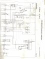
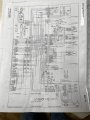
Can anyone tell more with the tech sheets I attached earlier?
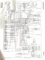
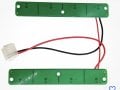
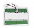
I can’t seem to find any other part that would affect it—since the light panel has a module within it that houses a power supply and another board I’d imagine is a LED drivers circuit. It has 110v feeding it and I believe it has feeds that run to the bottom drawer and freezer unit. Those lights do not have any problems. The first part I ordered was just two circuit boards with the LEDs on each, and connected together. Then the assembly plugs into the harness on the cabinet top. I didn’t realize mine was different—had the two LED boards, but also had the circuitry between them. So I ordered another part…this time the LED boards connected to the circuit module. Surely this would fix it, right? Nope. Very same problem. How could that be?? Although it seems it has less erratic flashing or they just quit for a period.
I’ve exercised the two door switches and I can’t see any kind of issue with them. But, the harnessing on the cabinet ceiling I’m wondering about—maneuvering them around in different ways it’s not a clear cause, but it’s all I have at this moment…
 

LesJones

Joined Jan 8, 2017
4,529
The first picture in post #28 shows that the 2 LED panels are connected in series but the picture in post #11 shows that each panel is connected to the driver board.I assume that post #11 is what you have. Did you try swapping over the two pannels as suggested in post #12 ? One other thing that you could try is to monitor the voltage between the wires at the panel when the panel is is working and when it is not working. If the voltage goes down when it is not working the the fault is on the driver. If the voltage goes up when it is not working then the fault is the panel. The is because the panels will be supplied from a constant current source. (NOT a constant voltage.) Your test with supplying them from a constant voltage source had the potential to destoy them.
Les
 

Thread Starter

robismod

Joined Sep 22, 2015
449
The first picture in post #28 shows that the 2 LED panels are connected in series but the picture in post #11 shows that each panel is connected to the driver board.I assume that post #11 is what you have. Did you try swapping over the two pannels as suggested in post #12 ? One other thing that you could try is to monitor the voltage between the wires at the panel when the panel is is working and when it is not working. If the voltage goes down when it is not working the the fault is on the driver. If the voltage goes up when it is not working then the fault is the panel. The is because the panels will be supplied from a constant current source. (NOT a constant voltage.) Your test with supplying them from a constant voltage source had the potential to destoy them.
Les
Thanks Les…
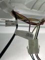
Post 11 pic is correct…post 28 I wasn’t clear—the left pic showed what I initially ordered, which was for a version that had the power and driver boards elsewhere, and only the lights were connected together to plug into the harness at the cabinet top. The right pic was my model—has the two panels separate and wired into the power and driver boards box.
I believe I swapped the panels and problem remained on that same side. I also did a test of applying a quick voltage to each light panel and they worked fine.
I’ve gotten away from this one for a bit and just last night was revisiting it again The flickering is still annoying and I’m still a little nervous messing with it—I HATE that SNAP/FLASH/SPARK when it happens; makes my heart nearly jump out of my chest! (I DO try to be careful but occasionally it happens) Looking back I recall I mixed up my power in the small harness in cabinet top—I ASSUMED the bigger gauge wires were AC…I know better now…
I’m still hung up on thinking it’s a wiring problem in/near the plug harness, and want to dig a little deeper with that, and also the testing you suggest…
I’ll look at it again today.
 

Thread Starter

robismod

Joined Sep 22, 2015
449
Did a little bit earlier…simply fiddled with the wiring, twisting, turning, etc., but no difference. But it did settle down a few times for a short period. (It’s done this all along but no long periods of constant flashing)
I’ll try later and try and measure the power.
 

LesJones

Joined Jan 8, 2017
4,529
When I want to measure something that is difficult to get to or there is risk of shorting something out with the meter probes I just solder some thin insulated wires to the points that I want to measure. That would have been difficult on the TDA3294 in your other thread but should be easy on the LED panels. You can then connect the other end of the wires to the test probes with some connector strip.
Les.
 

Thread Starter

robismod

Joined Sep 22, 2015
449
When I want to measure something that is difficult to get to or there is risk of shorting something out with the meter probes I just solder some thin insulated wires to the points that I want to measure. That would have been difficult on the TDA3294 in your other thread but should be easy on the LED panels. You can then connect the other end of the wires to the test probes with some connector strip.
Les.
Ok thanks Les…a little bit ago I did a similar deal—I made two small jumper wires that I was able to push into the back of the harness to contact the wires. That said, here’s what I have so far…
Meter on DC mode with leads onto the two DC wires: doors closed 4 vdc
Doors open 0.2–0.24 vdc with minus symbol flashing about every second on meter screen left. Nothing matched the intermittent flashing lights.

Meter in AC mode with leads onto the two AC wires:
Doors open 12.9 to 13.0 AC
Doors closed drops down to zero over about 1 second and stays there. Again, no reading matches/moves with the intermittent flashing. Keep in mind that sometimes the 3 lights in that panel go off and stay off for a short period; other times they’ll come on and stay constant for a short time. And then the flashing comes back…
 

Attachments

Thread Starter

robismod

Joined Sep 22, 2015
449
I’m still wondering IF…by chance this new board unit was a defective unit when I got it? Odd that it would be the same symptoms AND on the same side light panel. Seller didn’t have any more and none expected.
 

LesJones

Joined Jan 8, 2017
4,529
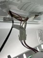
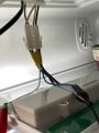
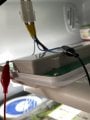
In post #34 you seem to be measuring the INPUTS to the LED driver module.I want you to measure DIRECTLY ON THE WIRES SOLDERED TO THE PANEL WITH THE 4 LEDs THAT ARE FLASHING. In the picture in post #1 the LED panels seem to be connected to the LED driver module with short wires soldered at each end. You need to measure the voltage where these wires are soldered to the LED panel.
Les.
 

Thread Starter

robismod

Joined Sep 22, 2015
449
In post #34 you seem to be measuring the INPUTS to the LED driver module.I want you to measure DIRECTLY ON THE WIRES SOLDERED TO THE PANEL WITH THE 4 LEDs THAT ARE FLASHING. In the picture in post #1 the LED panels seem to be connected to the LED driver module with short wires soldered at each end. You need to measure the voltage where these wires are soldered to the LED panel.
Les.
I thought you might say that…LOL…I’ll work on that…but get this—after the plugging, unplugging several times of the harness last night, and shoving those jumpers into the backside of the module harness, it’s been nearly perfect. The only glitch—for now—is when the doors are opened, there’s a very slight (almost unseen) “jitter” and they stay solidly lit. So far…I’ve looked at the pins in the harness several times and all appear tight with no issues…
 

wayneh

Joined Sep 9, 2010
18,136
...there’s a very slight (almost unseen) “jitter” and they stay solidly lit...
That may be unavoidable. I often notice a tiny delay when turning on LED lighting. Old incandescent bulbs felt like they started "instantly" despite the need for the filament to warm up. But LEDs have a perceptible delay. It has to be in the board and not the LEDs themselves, which are VERY fast.
 

LesJones

Joined Jan 8, 2017
4,529
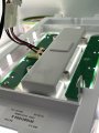
Until your post #34 I had assumed that the 4 LEDs on a board were connected in series but when you said that 3 of the 4 LEDs went out meant they could not be in series. I looked at the pictures of the boards and they seem to be in parallel. (There are no pictures of the other side of the LED boards so I am not absolutely sure.)
I have a different approach to faulting to you. I like to logicly trace back till I find the fault.
I don't think that a fault on the cable harness would effect only one of the LED boards.
I am assuming thet when the unit was working that the there was no situation when one of the LED pannels was on and one of them off. Is this assumtion correct ?
Les.
 
Top