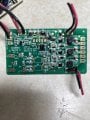
LED light panel in fridge

Thread Starter

robismod

Joined Sep 22, 2015
460
Until your post #34 I had assumed that the 4 LEDs on a board were connected in series but when you said that 3 of the 4 LEDs went out meant they could not be in series. I looked at the pictures of the boards and they seem to be in parallel. (There are no pictures of the other side of the LED boards so I am not absolutely sure.)
I have a different approach to faulting to you. I like to logicly trace back till I find the fault.
I don't think that a fault on the cable harness would effect only one of the LED boards.
I am assuming thet when the unit was working that the there was no situation when one of the LED pannels was on and one of them off. Is this assumtion correct ?
Les.
LOL…I wish I had your “logical” ability—I’ve mentioned before that honestly, I’m a “hack” or “Jackleg” as my late dad used to call us. Jack of all trades but master of none. And THAT is so true. LOL I’ve been very fortunate over many years of fixing most anything but in more recent years, the great guidance from guys like yourself has really come through, especially as things seem to be more complicated. So I try and muddle my way through and usually learn some of the basics along the way.
Let’s see…each panel has four LEDs. (There are attached pics in post #1)
Yes, after thinking about your thought about the wiring, yep, makes sense now thinking deeper, it would affect both panels…(and another late-breaking update—the lights are strobing again this afternoon)
And, the left panel always works correctly. It’s just the right panel. All of the 4 LEDs act the same way—strobing, flashing, jittering, short periods of OFF, etc., but the left panel never fails…
 
Last edited:

LesJones

Joined Jan 8, 2017
4,538
I can't think of a way to continue fault finding without measuring the voltage at the panel when the panel is working and when is flashing of off. Maybe someone else can suggest a way.
I have now found a picture of the other side of the board to the LEDs and re exmined the LED side of the board and am now going back to thinking that the 4 LEDs are in series. I also noticed that the groups of 25 plated through holes are to provide a thermal path between the copper on both sides of the board to improve the heatsinking for the LEDs,
Les.
 
Last edited:

Thread Starter

robismod

Joined Sep 22, 2015
460
I can't think of a way to continue fault finding without measuring the voltage at the panel when the panel is working and when is flashing of off. Maybe someone else can suggest a way.
I have now found a picture of the other side of the board to the LEDs and re exmined the LED side of the board and am now going back to thinking that the 4 LEDs are in series. I also noticed that the groups of 25 plated through holes are to provide a thermal path between the copper on both sides of the board to improve the heatsinking for the LEDs,
Les.
Ok here’s my latest findings for you.
Soldered some short wires onto the light panel board (on top of the existing ones) and:
When the 4 lights in the panel are ON, I’m reading 12.66vdc.
When the 4 panel lights are OFF, I’m reading 16.72vdc.
When I shut the doors the voltage drops to zero over about 1-2 seconds. All readings stay steady and do not fluctuate.
 

LesJones

Joined Jan 8, 2017
4,538
When you say when the lights are off in post #43 is this when they should be on ? If this is so then one (or more ) of the LEDs on the panel is going open circuit. (Or there is a connection on the panel going open circuit.) If you mesure the voltage between the connections to each individual LED the the one with the highest reading will be the faulty one.
Les.
 

Thread Starter

robismod

Joined Sep 22, 2015
460
When you say when the lights are off in post #43 is this when they should be on ? If this is so then one (or more ) of the LEDs on the panel is going open circuit. (Or there is a connection on the panel going open circuit.) If you mesure the voltage between the connections to each individual LED the the one with the highest reading will be the faulty one.
Les.
Yes, when that panel of lights go OFF, that’s with the doors open, and the other panel fully lit. (Yes, they should be ON, same as the other panel)

Whoa! So does that mean if ONE of the four LEDs on that affected panel is faulty, it would shut the panel down—and be the cause of this whole issue? I’ve been assuming it all stems from the Driver module.
 

LesJones

Joined Jan 8, 2017
4,538
This is because the LEDs are connected in series. Think of it like sets of christmas tree lights.(The old type that used incandecent bulbs.) When 1 failed the whole string went out.
Les.
 

Thread Starter

robismod

Joined Sep 22, 2015
460
This is because the LEDs are connected in series. Think of it like sets of christmas tree lights.(The old type that used incandecent bulbs.) When 1 failed the whole string went out.
Les.
Hmmmm…I’m trying to think back here…(dangerous lol)
I want to say that the replacement panels I had ordered earlier, that I tried soldering a new one it its place and it still acted up. But…I might have imagined that. I’ll try that again to be sure. And at the same time I could just put the old panel on the bench and apply DC to it and see what happens?
For right now, I ended up desoldering the panel from the wires and shrink wrapped them. Wife is happy the flashing has stopped and she says there’s still plenty of light. ☺
But…knowing me, I can’t just quit on it—I want to know what happened to it. LOL
 

LesJones

Joined Jan 8, 2017
4,538
If you measure the current flowing though the panel when it is woking (Or the working panel.) then calculate the resitance value that would develop a voltage of about 3.2 volts (The voltage across each LED when the panel was working.) across it with that current flowing though it. Then replace the faulty LED with that value of resistance. You would not loose much light with the loss of 1 LED. That would be easier thn looking through data sheets to find a suitable replacement LED.
Les.
 

Thread Starter

robismod

Joined Sep 22, 2015
460
If you measure the current flowing though the panel when it is woking (Or the working panel.) then calculate the resitance value that would develop a voltage of about 3.2 volts (The voltage across each LED when the panel was working.) across it with that current flowing though it. Then replace the faulty LED with that value of resistance. You would not loose much light with the loss of 1 LED. That would be easier thn looking through data sheets to find a suitable replacement LED.
Les.
Well…got back to it again earlier…I pulled the defective panel out and ran DC to it, and all 4 lights worked perfectly, and stayed constant for 15 min. before I pulled the power. I also pulled out the 4 other panels from the original and new ones I had ordered before this module—all worked fine.
So, it has to be in that driver module, right? (Which is tons of tiny small parts and I quit) Unless, I could somehow find just that module but having no luck so far…
 

LesJones

Joined Jan 8, 2017
4,538
You should use a limiting resistor in series with the LED panel (Or inividual LEDs.) to limit the current to within the current rating of the LEDs.
The test that you did in post #43 showed that the power supply was outputting 16.72 volts to the panel when the LEDs went out. You would expect the voltage of a constant current power supply to rise when there was no load on it. (Which it did.)
If you measure the volltage across each of the 4 LEDs when they are not working the the one with the highest voltage reading aross it will be the faulty one. If you then bridge that LED with a resistor of about 200 ohms then the three other LEDs on that panel should come back on.
The only other explanation would be if you were measuring the at the output of the power supply rather than at the panel then the fault was in the connection between the power supply and the panel.
Les.
 

Thread Starter

robismod

Joined Sep 22, 2015
460
You should use a limiting resistor in series with the LED panel (Or inividual LEDs.) to limit the current to within the current rating of the LEDs.
The test that you did in post #43 showed that the power supply was outputting 16.72 volts to the panel when the LEDs went out. You would expect the voltage of a constant current power supply to rise when there was no load on it. (Which it did.)
If you measure the volltage across each of the 4 LEDs when they are not working the the one with the highest voltage reading aross it will be the faulty one. If you then bridge that LED with a resistor of about 200 ohms then the three other LEDs on that panel should come back on.
The only other explanation would be if you were measuring the at the output of the power supply rather than at the panel then the fault was in the connection between the power supply and the panel.
Les.
Hmmmm…I’m really scratching my head here. Last night I used a 12v wallwart to power each of these 5 panels. I connected at the pads at the panel ends, same as where they were connected when being fed from the fridge modules located beside them. All worked great, no flickers, and stayed on the whole time I had them powered up. So…you’re saying I could still have a “defective” LED (still lights normally) but could still cause problems? Hmmmmm…
 

LesJones

Joined Jan 8, 2017
4,538
If your wqll wallwart is the older type with just a transformer, bridge rectifier and capacitor it will have very poor regulation so it will only give about 12 volts when it is loaded with it's rated current. At less than it's rated output current it will give a higher output voltage with no load it may go as high as 18 volts. If it is a modern switch mode type the output voltage will change very little between no load current and it's full load current.
I supect that your wallwart is the older type. As the opperating voltage of the panel with it's rated current is 12.66 volts them with an accurate 12 volts it would be quite dim. LEDs do not obay ohms law they behave in a similar way to a zener diode. A small change in voltage will cause a large change in current. As the measured voltage on the panel when it was not working was 16.7 volts if all e LEDs were OK then they would be VERY bright. I suspect that if you measured the voltage at the panels when connected to the wallwart it would be close to 12.7 volt as they would draw enough current to load your wallwart to drop it's ouput to about 12.7 volts. I agree that all the panels seem to be OK when connected directly to your wall wart. But if the power supply was faulty then the output would have to drop to stop the panel from working.
Les.
 

Thread Starter

robismod

Joined Sep 22, 2015
460
If your wqll wallwart is the older type with just a transformer, bridge rectifier and capacitor it will have very poor regulation so it will only give about 12 volts when it is loaded with it's rated current. At less than it's rated output current it will give a higher output voltage with no load it may go as high as 18 volts. If it is a modern switch mode type the output voltage will change very little between no load current and it's full load current.
I supect that your wallwart is the older type. As the opperating voltage of the panel with it's rated current is 12.66 volts them with an accurate 12 volts it would be quite dim. LEDs do not obay ohms law they behave in a similar way to a zener diode. A small change in voltage will cause a large change in current. As the measured voltage on the panel when it was not working was 16.7 volts if all e LEDs were OK then they would be VERY bright. I suspect that if you measured the voltage at the panels when connected to the wallwart it would be close to 12.7 volt as they would draw enough current to load your wallwart to drop it's ouput to about 12.7 volts. I agree that all the panels seem to be OK when connected directly to your wall wart. But if the power supply was faulty then the output would have to drop to stop the panel from working.
Les.
Whoa! I’ll have to sort through this more…
But what about the LED driver board? If the Power board is ok, then wouldn’t the driver board possibly have an issue? (This pic is of the original that I fried I think)
 

Attachments

Top