OK, and it seems that a source of PWM control was on hand, but the logic sense required appeared to be the opposite. At that point, the CD4049 HEX INVERTER IC would appear to be able to provide the inversion with adequate drive capabilities.
IFF that really is the case, possibly the solution is at hand.
TS does not know much about inner workings which is why he is asking for help. control of load or in thins case LED brightness can be done two ways:
a) using PWM
b) using analog
problem with analog is dissipated power. so everywhere one looks and sees dimmable LEDs, it is the PWM at work.
but... one need to take into consideration power (voltage and current). DMX controller only provides signal. actual dimming still requires something... a MOSFET or whatever driver... to drive the load.
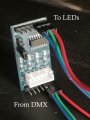
in this case DD311 is exactly that. the small resistor that connects to DD311 is simply used to adjust maximum current for the load (100% brightness). the EN input is used as PWM input.
optionally if the DMX controller has open collector output output (can be added externally), it can connect to that DD311 resistor as well, bypassing EN input. but this is more of a troubleshooting tip in case something is wrong with EN (stuck on).
the real problem is TS wanted to bypass DD311... and drive those power LEDs directly from DMX controller which cannot work. for that to work, one would need to add own current limiting and own power mosfets... like in post #37.
but since DD311 are working, there is no need to bypass them. just need to interface to them...
I'm really sorry a lot of this I just don't understand, the dmx control handles dimming flashing on led strip lights without any other components so my simple brain thinks I just need to treat these as just leds the resistors (as on the strip lights are on the fixture) so could I connect the positive then find the negative input after the control chips on the fixture ignoring them completely and treating the leds as if they are part of a strip, this seems to have got so complicated overlooking the simple solution or am I totally wrong tbh I'm about to bin it, lifes just too short, I really do appreciate peoples time and expertise but you are explaing it to a caveman. I really do wish I understood more of the diagrams etc and I can only apologise.
Those resistors on the fixture are not wired the same as on a LED strip.
They control the current through the DM311 chip.
To modify the fixture as you see it requires a higher wattage resistor in place of the DM311.
I'm really sorry a lot of this I just don't understand, the dmx control handles dimming flashing on led strip lights without any other components so my simple brain thinks I just need to treat these as just leds the resistors (as on the strip lights are on the fixture) so could I connect the positive then find the negative input after the control chips on the fixture ignoring them completely and treating the leds as if they are part of a strip, this seems to have got so complicated overlooking the simple solution or am I totally wrong tbh I'm about to bin it, lifes just too short, I really do appreciate peoples time and expertise but you are explaing it to a caveman. I really do wish I understood more of the diagrams etc and I can only apologise.
While this may seem complicated it can be greatly simplified if you consider the LED fixtures as black boxes that just need signals to tell them to turn on, and how brightly.
The MOSFETs are just switches. When you apply a sufficient voltage to one of the pins (called the Gate), they turn on.
The chips on your board incorporate a MOSFET but also provide some additional control. The EN (Enable) pin is a much easier to use switch that allows the MOSFET to be easily switched on and off. When EN is "pulled low", that is, connected to ground (0V) the LED is turned off. When it is "pulled high", that is, connected to V+ (3.3V), the LED is turned on.
The DMX controller can provide the signal for the EN pin and the result would be much better than trying to drive the LEDs directly since the actual power supply for the LEDs is the +11V input. This means it doesn't matter how big the conductors coming from the DMX controller are, since they will not carry the current for the LEDs.
If you follow @sghioto's instructions for connecting it this way, you will have a solid setup with that local power supply advantage. It isn't as complicated as it feels. I think with a little effort to ignore your preconceived notions of how it "should" work you can do it.
It all depends on if you are able to wire up the inverter circuit.
However I believe this stepper motor Module can perform the logic inversion required.
got 10 (I think I need 8 in total) altogether got the ones with motors as they had the cable attached only about £20 and some dupont cables to connect the input side I will glue them in for stability when it all works
got 10 (I think I need 8 in total) altogether got the ones with motors as they had the cable attached only about £20 and some dupont cables to connect the input side I will glue them in for stability when it all works
Yes thought I mentioned that theres 8 individual lights all with the same board in each thats why I'm using a 24 channel dmx controller. Why does it changes?
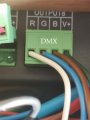
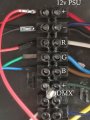
ok I have wired 1 light board as above see images. no control over the light just stays on red as it does when just the positive and the negative are connected. I tried using the positive from the DMX made the lights a bit dimmer, I also tried removing the negative to use the negatives on the leds this showed no lights at all, any ideas?
 Facebook
 Google
 GitHub
 Linkedin