LED help

Thread Starter

Thedax

Joined Oct 22, 2025
148
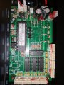
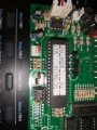
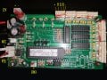
I can't see how this would work I don't want to use the control chipscat all as this will be handled by the decoder I simply need to connect the leds the chips are of no use and need removing or disabling. I want to treat the leds like a mini strip with 3 coming on at once using the decoder which it is designed for it has only 4 connectors 1 POS+ 3 NEG R G B,not five like the current board, if I wire it the was you say maybe I will get the lights to come on but I will have no control over them possibly damaging the decoder as well. Have I miss understood?
 

MisterBill2

Joined Jan 23, 2018
27,519
It is clear to me that a whole lot is not clear.
First, exactly what are the intended control signals? That is, what are the control signals that were telling the now-failed controller what to do? AND then, just what are the signals required by the logic on the LED circuit boards??
What it looks like to me is that the LED circuit boards only require command signals, not power control. THAT is why they require connections of both of the supply power feed. It looks like the proposed controller is intended to directly control the standard LED strips, which have no logic present on the strip, but only LEDs and resistors. SO the replacement control board is totally the wrong type. What is required is not clear because we have no hint about what control signal those LED boards actually require.
 

sghioto

Joined Dec 31, 2017
8,634
Ok before I do any more to this fixture as I seem to be going around in circles, could someone please explain why I need the mosfets/switches?
LEDs require current limiting. You can't just hook them up directly to 12 volts. The chips act like a resistor limiting the current to a fixed amount which is most likely set by those 3 resistors.
I'm try to figure how the RGB wires are connected to these chips but need your help to verify.
Again, do the following test.
Connect 12 volts and Neg to the fixture, all RGB wires not connected.
In post #12 you said "When the 12v + is in and the negative (so none of the RGB are connected) all the lights turn on."
Now connect the R wire to negative and see if the Red Leds turn OFF please.
If they do then try doing the same with G and B wires.
 

Thread Starter

Thedax

Joined Oct 22, 2025
148
I havent been able to get to the main unit yet but in the mean time I came across this circuit board that is identical to the broken one hoping this might help if not I will be able to test in Mon /Tues next week. Thanks for all your understanding and patience with me so far
 

Attachments

Thread Starter

Thedax

Joined Oct 22, 2025
148
This is for context this board is useless and doesnt do what I want it to do, I want to repurpose the unit not using those mosfets on the other board as I dont need the switching as thios will be handled by the 512DMX box, and thus I can control fully the LEDs I can show the traces with a multi meter if it helps. I wondering if I can power the leds through the existing wiring going throught the resistors on board if not I can rewire it to new resistors then to the LEDs so that it all works. Think theres been a bit of confusion between fixing and repurposing and thats my fault will do the test you suggested early next week :)
 

MisterBill2

Joined Jan 23, 2018
27,519
I havent been able to get to the main unit yet but in the mean time I came across this circuit board that is identical to the broken one hoping this might help if not I will be able to test in Mon /Tues next week. Thanks for all your understanding and patience with me so far
OK, and thanks for the PIX! One thing is quite clear looking at the pictures is that I see no power devices. That backs up my thinking that THE CURRENT LIMITING IS IN THE LIGHT ASSEMBLY. THAT means that you DO NOT need to do current limiting because it is already present in the light assembly. THAT IS PART OF ALL THOSE IC DEVICES WE SEE . So one potential problem is GONE.The fact that there are five connections, including +12 and the common return, plus three color inputs, implies that the colors get control signals, which might be variable voltages or varying duty cycles, or possibly binary data bursts. OR a secret code. All using the power common as the return reference.
 

Thread Starter

Thedax

Joined Oct 22, 2025
148
" If my theory is correct no modification of the existing light fixture will be needed but possible a simple supplemental circuit maybe required"

Hi Guys finally found some time to test these theories, and not exactly but close

So I powered the fixture only from the 12v supply ignoring the DMX controller completley. in this configuration the red and the blue lights came on only, all RGB disconnected, when I touched the green negative with my fingers the green lights came on (wasnt expecting that) when I connected them all to ground all lights went off!Hopefully the result we WERE expecting :)
 

MisterBill2

Joined Jan 23, 2018
27,519
OK, post #31 verifies that the control and current limiting is all on the light fixture, and thus what the main control system must do is supply the control signals, NOT provide actual LED driver functions. Quite a bit of difference.
BUT duplicating the functions of the original control board will be a challenge because we really do not know just what it did.
The pictures in post #26 tell us that it is rather complex.
 

sghioto

Joined Dec 31, 2017
8,634
when I connected them all to ground all lights went off!Hopefully the result we WERE expecting
Exactly the results I was expecting.
But here's the thing it's the opposite of how the DMX controller works meaning the DMX pulls the RGB lines to negative to activate the LEDs.
Without modifying the LED fixture a simple inverter circuit is required to convert the signal from the DMX.
This is the supplemental circuit I was speaking of and can be implemented in several ways.
Using discrete transistors or IC chips:
1761488203407.png
 

MisterBill2

Joined Jan 23, 2018
27,519
The interface may not be that simple, if the control signal includes any analog information. The drawing in post #33 does not actually tell us what the control signal is.
 

Thread Starter

Thedax

Joined Oct 22, 2025
148
I would think its analogue as its from 2006, it also didnt have much function or real control via DMX maybe I should just rewire the whole thing!
 

panic mode

Joined Oct 10, 2011
4,982
...when I connected them all to ground all lights went off!Hopefully the result we WERE expecting .
why not? it is exactly what you were told (including post #15)

DD311 is simply replacing high power series resistor to LEDs and mosfet, compare this with circuit on the right.
1761506859884.png
 

MisterBill2

Joined Jan 23, 2018
27,519
OK, so now it is clear that what we need to know is what sort of control input that DM311 IC needs. Are the three colors simply ON/OFF controlled, or is dimming available?? OR is the dimming done with a PWM scheme?? I am asking because that controller PCB has a processor and quite a few other ICs on it. Hopefully the TS can tell us what control functions are available from that board.
 

MisterBill2

Joined Jan 23, 2018
27,519
See first sentence in post #28.
PWM is the control scheme using the DM311
The first post, verbatim:" This is for context this board is useless and doesnt do what I want it to do, I want to repurpose the unit not using those mosfets on the other board as I dont need the switching as thios will be handled by the 512DMX box, and thus I can control fully the LEDs I can show the traces with a multi meter if it helps. I wondering if I can power the leds through the existing wiring going throught the resistors on board if not I can rewire it to new resistors then to the LEDs so that it all works. Think theres been a bit of confusion between fixing and repurposing and thats my fault will do the test you suggested early next week :) "
I don't see anything about PWM.
For inverting the logic, a CD4049 CMOS Hex inverter Inverter has a much stronger pull down than most CMOS, so I suggest using one of those to do the inverting. Much smaller than the group of transistors, and simpler to wire.
 
Top