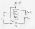
A 556 dual timer, about a dozen or so resistors, about half a dozen capacitors, a switch, a power source, and your LED.
A microcontroller could do it with fewer components, buy you need to be able to program the microcontroller (write the program and load it onto the microcontroller).
At dinner right now but imagine a 555 astable using 1 cap and 1 resistor. Another cap and resistor from pin 4 to ground. A momentary switch from pin4 to Vcc and a resistor for the LED.
At dinner right now but imagine a 555 astable using 1 cap and 1 resistor. Another cap and resistor from pin 4 to ground. A momentary switch from pin4 to Vcc and a resistor for the LED.
I thought of that.
The minimum reset voltage is 0.4V and the maximum reset current is 0.4mA, so the minimum resistor value is 1kΩ, so since it takes about 2.4 time-constant to drop to 0.4V from a 5V supply, the capacitor value would be a large 2mF for a 5 second on-time.
Given the sensitivity of that circuit to the small reset voltage and the time-constant, getting a reasonably stable 5 second period would seem to be problematic.
A 556 circuit may be best for minimum parts.
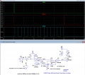
Below is the LTspice sim of a circuit using one CD4093 quad Schmidt-trigger NAND gate chip and one small MOSFET LED driver:
R3 and D2 are to avoid the otherwise long first pulse width.
The input latch insures that the last pulse is not truncated.
The normal first and last pulse-widths are not critical to have, but they are a nice feature of the circuit, which the 555 circuits may not have.
You can eliminate the MOSFET and drive the LED with the U1 output directly if a high brightness LED operating at a few mA gives sufficient brightness.
I think the above post #18 is really a great way to resolve this application as it demonstrates a good use of the logic parts.
But it all depends on what you regard as "Simple".
This to my mind is simple...
But the complexity is in the writing of the program and the programmer hardware required.
This question reminds me of one a couple of years ago when a poster wanted to make a "Simple Video Camera" from the ground up.
Purchasing a pre-made board, like with the ESP32CAM is simple, but to build a camera from logic and analog parts is not. (I had done just that in the past and it did not work very well).

 Facebook
 Google
 GitHub
 Linkedin