Learning about Integrators

Thread Starter

scott ryan

Joined Apr 2, 2023
5
Hello -

I am new to learning about electronics - but I am not very good at math.

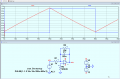
I am currently trying to build an op amp integrator. The attached circuit, sourced from Wikipedia, purports to work slightly better than the standard. I am assuming Rl and Rn are mainly based on dealing with specific circumstances, so I'm not including them in the current design.

I have two primary questions here:

1. If I want to adjust the time-constant, does it matter if I change Ri, rather than Cf? Or does it ultimately produce the same result, regardless of which component is changed?

2. How do I determine the value for Rf?

Thank you.EG57_ 732.png
 

Attachments

Last edited by a moderator:

LvW

Joined Jun 13, 2013
2,026
Most important:
Do you know the purpose of each part ?
Are you familiar with the expression for the inverting gain of an opamp circuit?
What is the transfer function of the shown circuit?
 

Ian0

Joined Aug 7, 2020
13,131
For an integrator made with perfect components only Ri and Cf are needed in addition to the op amp, and only the product Ri.Cf matters.
Everything else is to make the best of real life op-amps. Rn (which should be the same value as Ri) compensates for bias current. Use a JFET op-amp with almost zero bias current and you can delete Rn.
Rf deals with offset voltage, by moving the problem elsewhere. Even a small constant offset voltage will turn into a big error if it is integrated for long enough. Rf deals with it by making it not such a good integrator at low frequencies. The lower the input offset voltage of the op-amp the larger value of Rf you can use.
 

WBahn

Joined Mar 31, 2012
32,823
It's been a long time since I've done an integrator, but shouldn't Rn be equal to the parallel combination of Ri and Rf, since that's the resistance seen by the inverting input?

Hopefully Rf will be high enough that Rf can be neglected without much impact.

As for whether to change Ri or Cf, that depends. Both have a practical range of values that they can be and if you go outside that range, certain non-ideal behaviors will become noticeable of even dominant. Part of that is due to interactions with the non-ideal opamp, and part of that is the frequency content of the signals you care about.
 

Ian0

Joined Aug 7, 2020
13,131
It's been a long time since I've done an integrator, but shouldn't Rn be equal to the parallel combination of Ri and Rf, since that's the resistance seen by the inverting input?.
Assuming an amplifier with perfectly balanced bias currents then that would be correct. Also, if Rf were much smaller than 20x Ri then it wouldn’t be much of an integrator, more of a low-pass filter; and if Rf>20Ri then the nearest E24 value for Rn would be Ri.
 

WBahn

Joined Mar 31, 2012
32,823
I'm thinking more of the general case. I don't want the TS to end up thinking that Rn is always equal to Ri for any opamp circuit.
 

LvW

Joined Jun 13, 2013
2,026
Assuming an amplifier with perfectly balanced bias currents then that would be correct. Also, if Rf were much smaller than 20x Ri then it wouldn’t be much of an integrator, more of a low-pass filter; and if Rf>20Ri then the nearest E24 value for Rn would be Ri.
Its even worse - in reality there is not an (ideal) integrator.
Even without any feedback resistor (in parallel to the C) the circuit is a lowpass circuit due to the limited open-loop gain Aol of the opamp (however, with a very small 3dB-cut-off).
More than that, any real opamp will add unwanted phase shifts to the circuit - with the consequence that there will be only one single frequency where the total phase shift of the circuit is 90 deg. (Remember: An ideal integrator requires a phase shift of 90 deg over the whole desired integrating range).
Therefore, the feedback resistor should be selected as large as possible (with respect to the desired "integrating" range).
 

MrChips

Joined Oct 2, 2009
34,807
Op-amp Integrator

1680530215175.png

1680530264937.png

This is an integrator using ideal op-amp characteristics.
If there is any input offset voltage in the op-amp the output will saturate at one of the power supply rails.
The purpose of Rf in parallel with C is to provide a discharge path in order to avoid going into saturation.
Rf should be greater than 20 times R.
 

LvW

Joined Jun 13, 2013
2,026
This is an integrator using ideal op-amp characteristics.
If there is any input offset voltage in the op-amp the output will saturate at one of the power supply rails.
The purpose of Rf in parallel with C is to provide a discharge path in order to avoid going into saturation.
Rf should be greater than 20 times R.
I like to add that such a parallel resistor is not needed when the circuit is part of an overall negative feedback loop (as is often the case for filter and oscillator circuits as well as for a large variety of control systems)
 

Thread Starter

scott ryan

Joined Apr 2, 2023
5
As for whether to change Ri or Cf, that depends. Both have a practical range of values that they can be and if you go outside that range, certain non-ideal behaviors will become noticeable of even dominant. Part of that is due to interactions with the non-ideal opamp, and part of that is the frequency content of the signals you care about.
I think I understand that the ratio of Ri to Cf produces a frequency that will either make things integrate faster or slower. What I'm still a little confused about, though, is whether I can just put a potentiometer in place of Ri to tune across a wide range, or if there will be other complications.
 

Ian0

Joined Aug 7, 2020
13,131
I think I understand that the ratio of Ri to Cf produces a frequency that will either make things integrate faster or slower. What I'm still a little confused about, though, is whether I can just put a potentiometer in place of Ri to tune across a wide range, or if there will be other complications.
Not the ratio, the product, and yes you can use a pot. Keep it between 1k and 1M for best results.
The product of a resistance and a capacitance is time:
Ohms = Volts/Amps
Farads = Amp.Seconds/Volts
Ohms x Farads = Seconds.
That's why you see the term "time constant" referring to a resistance and a capacitance.
 

LvW

Joined Jun 13, 2013
2,026
I think I understand that the ratio of Ri to Cf produces a frequency that will either make things integrate faster or slower.
Neither Ri nor Cf nor both together "produce a frequency" - rather, the product Ri*Cf acts as a time constant which determines the integration properties (0dB-crossover in the frequency domain)
 
Top