Leak detection circuit

Thread Starter

PF Graham

Joined Sep 25, 2022
28
Hi All,

I'm working on converting EVERY SINGLE vintage Jeep into fully EV - 'oh the humility...

But, yes, that's what I'm doing (4x4evc.com). Working on slightly smarter battery boxes, specificaly the Back Battery Box - here's a quick snap:

1734576799763.png

I'll be more then happy to fill in the site on the specs if anybody cares.

This one site where the gas tank was in a CJ-7, pretty low and 100% exposed to the elements, water especially.

The good folks over at Amphenol came up with this new Leak Detection Sensor (p/n BAF147B002-00A0), here is their basic circuit:
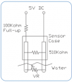
1734577114638.png

I don't get it, sorry, I feel stupid. What I'm looking for is a simple circuit that will light an LED to indicate that the sensor 'sees' water.

I have the sensor, a 12v to 5v converter, 4,000 LEDs of varying color (slight exaggeration...) and a little cup of water.

Any help would be appreciated. The specs for the sensor are below.

Thanks,
Patrick

Specs:

1734577176907.png
 

Ya’akov

Joined Jan 27, 2019
10,231
Welcome to AAC.

The datasheet for the part explains:

BAF147B002-00A0 Datasheet said:
Thermometrics Water Detection Sensor detects moisture leakage via a change in resistance value of the sensor and feeds a signal to the Battery Management System (BMS) to warn the driver.
So the sensor requires a circuit that detects the change in resistance. Unfortunately, the datasheet does not provide threshold values, nor any application notes. It appears it is specific to a particular BMS.

It also goes out of its way to say not to expose the sensor to water, and that it is disposable, so once it provides a warning it must be replaced. I am not sure it is a good way to provide this function for your custom battery. There are other moisture sensors that would probably be easier for you to use.

Researching leak sensors or something similar should get some stuff that can direct you to other options.
 

Thread Starter

PF Graham

Joined Sep 25, 2022
28
Welcome to AAC.

The datasheet for the part explains:


So the sensor requires a circuit that detects the change in resistance. Unfortunately, the datasheet does not provide threshold values, nor any application notes. It appears it is specific to a particular BMS.

It also goes out of its way to say not to expose the sensor to water, and that it is disposable, so once it provides a warning it must be replaced. I am not sure it is a good way to provide this function for your custom battery. There are other moisture sensors that would probably be easier for you to use.

Researching leak sensors or something similar should get some stuff that can direct you to other options.
WTF!!!

I did NOT see that in the 'Notes' section at the bottom of page 4!!!

Couple things - if this is correct, this sensor from Amphenol is 100% useless in EV settings. Just the time to take down the battery box is measured in hours.

Second, there is no setting in any BMS (Orion or Thunderstruck or Delirium) for water leak detection. What the hell are they talking about????

GREAT CATCH, I'll reach out to my TE and Amphenol reps now - 100% unacceptable.

THANK YOU so much for your time and effort on MY project, a HUGE THANK YOU!

I'll follow up after my calls, there's no way they are this stupid....

- Patrick
 

Thread Starter

PF Graham

Joined Sep 25, 2022
28
Okay, first thoughts of the day....

Deep breath, okay. I think I get it. I don't like it and I'm not sure it makes sence but, I get it.

Haven't talked to my reps yet but, I kinda' get it.

So, let's play a mind game - if the sensor detects water in the battery box, you have to remove the battery box. Full stop.

Because this is designed as the Back Battery Box for the Jeeps, I included a drain plug in one of the corners, you know, just in case the leak detection works, I would instruct the owner to pull over, put the Jeep in a slight uphill park and open the drain to let the water out.

The logic here is to save the battery packs if a small amount of water has pooled more then 1/8" inside the Box.

REGARDLESS, you would have to drop the Box and inspect it.

There are only two things that can cause water to be in the Box:
1) Internal leak from the cooling loop of the Tesla Battery modules (pretty damn rare and most likely an assembly failure).
2) You hit a puddle. Okay, maybe a BIG puddle or whatever, the water came INTO the Box from the outside.

#2 seems like the most likely occurrence. If you follow the instructions (that I haven't written yet...) and pull over, drain the Box, you should observe how much water comes out. If it's a trickle, as in, some water was forced in through one of the 3 holes in the Box (ingress holes: BMS -signal, Cooling, HV Cable) then it's probably not much and you can drain it and limp home to drop the Box in the comfort of your garage or hovel or whatever.

Okay, I get it now. Let's assume it's #2, and the water is coming in from outside the box, well, it's probably not potable, probably VERY NOT potable so, even if you drain it, save the modules, the two contacts on the bottom of the sensor can and will be coated by the dirty water. I can see that this might interfere with future leak detections - right?

So, without talking to my reps, I get it.

Once you drop the Battery Box, 'cause you should at this point, it would take seconds to replace the $12 (now down to $8!) sensor. I'll add a 2 pin Deutsch connector inside the Box so you can replace it without having to run a new set of wires through the Battery Box itself (I've got the two wires in the BMS wire bundle).

Am I on the right mental track on this - check me here gang.

As for the buried 'Note', that's deeply deceptive and poorly written. Even if it's 'disposable', you need to know that up front so you can build in a design to easily remove it should the occasion arise.

- Patrick
 
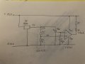
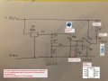
This circuit lights-up the Led when low resistance is detected.
The 10k potentiometer sets the trip-point at what resistance the Led lights-up.
LM393 is a comparator IC in DIP package.
IMG_1335.jpeg
 

Thread Starter

PF Graham

Joined Sep 25, 2022
28
This circuit lights-up the Led when low resistance is detected.
The 10k potentiometer sets the trip-point at what resistance the Led lights-up.
LM393 is a comparator IC in DIP package.
View attachment 338446
You know what pisses me off, I can tell you did this on the back of a napkin or scrap of paper and it looks like it was a first draft.

I'll pull all the parts apart and spend a hour figuring it out and you did it in seconds (assume).

Here's a video of my version from last night -
.

It works but kinda'. I'm didn't including he 100k ohm Pull Up resister (mostly because I don't have or understand it, I'll buy a handful now...).

THANK YOU, I'll start to figure out what you did now.

- Patrick
 

MisterBill2

Joined Jan 23, 2018
27,432
OK, and a very interesting project and a more interesting concept.
Now some questions: What sort of jeep?? The jeeps that I have ridden in with friends would visit interesting places where a normal car could not go. And climbed into spots that normal cars could not even dream about. And been refueled by folks lugging in gas cans because there was no other way to bring them in. No roads, no paths.So what sort of range would this electric jeep have, and what sort of capabilities would it have??
For the back battery box, if it is indeed liquid cooled, how about a water-PROOF box flooded with non-conductive coolant, so that water simply could not enter??Like has been done with some power electronic assemblies. BUT NOT!! filled with transformer oil. (that is nasty!) A sealed, flooded, enclosure would keep any water or moisture out, and aid cooling by conducting heat to the tank surface. Cooling like some hydraulic systems.
AND, how much weight will the battery packages weigh.
 

Thread Starter

PF Graham

Joined Sep 25, 2022
28
[/QUOTE]
Is this about right
This circuit lights-up the Led when low resistance is detected.
The 10k potentiometer sets the trip-point at what resistance the Led lights-up.
LM393 is a comparator IC in DIP package.
View attachment 338446
Okay, does this look right:
2024-12-19 13_24_55-IMG_1335 (Large).jpg

Here's the parts list as far as I can figure it:
1734647260069.png

I don't understand how to attach the comparator, I can see the Vcc pin but a little unclear about how to hook up the rest of that.

Am I close?

- Patrick
 
Last edited:

Thread Starter

PF Graham

Joined Sep 25, 2022
28
OK, and a very interesting project and a more interesting concept.
Now some questions: What sort of jeep?? The jeeps that I have ridden in with friends would visit interesting places where a normal car could not go. And climbed into spots that normal cars could not even dream about. And been refueled by folks lugging in gas cans because there was no other way to bring them in. No roads, no paths.So what sort of range would this electric jeep have, and what sort of capabilities would it have??
For the back battery box, if it is indeed liquid cooled, how about a water-PROOF box flooded with non-conductive coolant, so that water simply could not enter??Like has been done with some power electronic assemblies. BUT NOT!! filled with transformer oil. (that is nasty!) A sealed, flooded, enclosure would keep any water or moisture out, and aid cooling by conducting heat to the tank surface. Cooling like some hydraulic systems.
AND, how much weight will the battery packages weigh.
Thanks, we think this is interesting also!

Replies to Questions:
- We only do Jeeps - CJ-7 & Scrambler, YJ and TJs (1980 to 2006). We'll add to that lineup once they begin to age out or a customer brings us a newer one.
- 110 - 118 miles range (37.1 kWh total battery pack). Remember, when scratching your head as to the viability of a 100 mile range Jeep, when you take it off-road, like in your question above, you don't go far, you only travel short distances. A long weekend trek could be no longer then 25 miles in total off-road distance. ICE motors are HORRIBLE off-road compared to EV - two reasons: no idleing and 100% torque at 1 rpm! You could drive all day and power then camp at night and never need a charge.

Total weight is 3 modules @ 60lbs ea plus the enclosure (Battery Box) @~ 30lbs - 60x3 + 30 = 120ish lbs.

No, we won't be filling it with anything. 1,000 reasons that's not a viable solution but the simplest is: it becomes un-serviceable.

It is already designed to be IP66 waterproof. I worry, that's what people like me do, worry about every little thing.

Interesting idea, I get it, but no, not that.

- Patrick
 

Thread Starter

PF Graham

Joined Sep 25, 2022
28
A quick snap for all you wire nerds (me included):
1734649279297.png

I've got this one torn apart to do some plumbing for the cooling loop and because I just moved shops, I wasn't able to finish swapping out the portions of this build that are in prototype plywood with 6061 Aluminum.

Quickly, from the firewall forward:
- Tech Box - containing Inverter, LV-JB (low-voltage junction box),
- Cooling box - hookup for all the cooling and where I've place the 12v battery
- Cooling fan - the motor is air cooled but, the inverter, battery modules and the soon to be upgraded Combo OBC, all need to be on the cooling loop
- The Front Battery Box - it usually sits on top of the Cooling Box
- Left side is the OBC (On Board Charger)
- Right side is the Volvo self contained P/S (Power Steering) pump

- Patrick
 
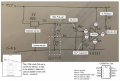
A 10uF (microfarad) capacitor removes the noise when you are turning the potentiometer. It’s a good manner to use it.

A 10k Potentiometer you have choose seems ok to me.

A 1k in series with Led limits the Led current to 10mA. No Led driver is needed, just 1k resitor and Led if a basic/common 20mA Led is going to be used.
If you want to use a higher power Led the driver is needed then.
Note: Todays 20mA Leds glow nice at 10mA, a 20mA is Led maximum rating so I picked a 10mA reserve.

A LM393:
Pin4 is ground, Pin8 is +12V, Pin2 is potentiometer viper, Pin3 is sensor output, Pin1 is Led cathode.

A 100k pull-up resistor in sensor is essential.
 
Last edited:

Thread Starter

PF Graham

Joined Sep 25, 2022
28
A 10uF (microfarad) capacitor removes the noise when you are turning the potentiometer. It’s a good manner to use it.

A 10k Potentiometer you have choose seems ok to me.

A 1k in series with Led limits the Led current to 10mA. No Led driver is needed, just 1k resitor and Led if a basic/common 20mA Led is going to be used.
If you want to use a higher power Led the driver is needed then.
Note: Todays 20mA Leds glow nice at 10mA, a 20mA is Led maximum rating so I picked a 10mA reserve.

A LM393:
Pin4 is ground, Pin8 is +12V, Pin2 is potentiometer viper, Pin3 is sensor output, Pin1 is Led cathode.

A 100k pull-up resistor in sensor is essential.
Got it (I HOPE), here's a revised block diagram. Can you check to see if you accidently placed the Pull-up inside the sensor, it's not inside, they just show it close to the case, let me know.
1734661798562.png
Thanks.

- Patrick
 
You are right Patrick, the 100k pull-up is outside the sensor.
It should be depicted outside of dashed box.
Your schematic is correct.

What 5V regulator are you good to use btw?
 

Thread Starter

PF Graham

Joined Sep 25, 2022
28
You are right Patrick, the 100k pull-up is outside the sensor.
It should be depicted outside of dashed box.
Your schematic is correct.

What 5V regulator are you good to use btw?
Cool - just making sure.

The 5v regulator is on the video, I just got home, I'll look it up in a sec...
 
Last edited:
Top