LC Filter for three phase inverter

Thread Starter

Prithvi10

Joined Apr 1, 2019
31
Hi ,

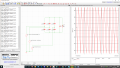
I am designing a closed-loop sine pwm three-phase inverter with an output power of 60kVA with a phase RMS voltage of 115. I am struggling to design the LC filter for the system to convert the square wave output into a sine wave. Please help with the design of the filter.

Thank you.

Regards,
Prithvi
 

WendellB

Joined Feb 14, 2020
22
Hi Prithvi10 and Marc too

Obviously looking at both you issue and the power level of 60kva, your a professional.
I agree with Marcs sound request for more details.

You design issue namely filtering a square wave using a passive LC Filter got my attention for I have solved a similar problem
a couple of times during my career. One possible solution is to use an OTT filter to convert the square wave signal into a sine
wave with less than 1% total harmonic distortion even if the load resistance is changed by a factor of 1 to 100, in other words
if the load is varied from full load 100% to 1% of full load. The Idea was not mine. It was developed in the mid 50s by an
Engineer named OTT working at or associated with GE and documented in their booklet on page 178. Their booklet
is entitled: "Silicone Controlled Rectifier Manual" published in 1964. Mr. Ott used his technique to replace 400 hertz rotary
generators with SCR square wave inverters driving an an Ott filter to provide clean sinusoidal power at 400 hertz, almost
what you propose to do except at 60 hertz.

Within the last 7 years I proposed a similar solution to a military customer of the Prime contractor I worked for and below are a
couple of pages of my initial proposal. Since it was military I removed all other pages with sensitive information.

The actual OTT filter topology consists of two coils and two capacitors. At 60 herts the core material for the inductors is going
to be fairly expensive, probably consisisting of Grain Oriented Silicon Steel, or Possible Mu-metal. but I am sure you already
know that. The design equations for the OTT filter are on page 178 of the referenced document. I would be happy to show
the performance you would expect using an LTspice schematic consisting of a square wave driver, an OTT filter and a load.

You will be driving the filter with a square wave. However as you see below. A 33.4% duty cycle provides the cleanest signal
other than a sine wave, of course, to drive any filter when isolating the fundamental frequency.

Good luck with your project, keep save from the Corona Virus.

Best regards

Wendell, a retired Power Electronics Engineer, level 5

1590163856104.png

1590163923427.png
 

Thread Starter

Prithvi10

Joined Apr 1, 2019
31
Could you provide a schematic of your intent? Include loads on each of the phases.
Hi,

I have attached the schematic of my circuit. It is actually a dc link converter. As i mentioned already i have issue in designing the filter for the system. My output frequency is 400Hz with power of 60kVA and phase voltage of 115V RMS.

Thank you
 

Attachments

WendellB

Joined Feb 14, 2020
22
Hi Prithvi10,

The circuit you sent is a block diagram, not a circuit with circuit values so I cannot use it.

You said in your initial description of the task that you planned to drive a filter with square waves and needed a filter to convert
the square waved into sine waves. Further, the square waves were broken up into 3 phases so you could produce 3 phase
sinusoidal voltage at a power level of 60kw.

I can design the filter to get you started but, as I said before, I do need a simple schematic in LTspice showing just the
connection of the three square wave generators to the three bandpass filter, (they can be shown as three blocks called FILTER.
And the resistive loads, three of them at the output of the filter. Then I can design the filters, show you how, And calculate the performance of the circuit. For example, the total harmonic distortion over load swings.


One reason I ask for schematic details is that the filter topology may have to be symmetrical not single ended. Makes a
difference in the inductance values. Also the LTspice circuit can yield a lot of valuable performance data.

LTspice is a very popular, easy to run electrical circuit analysis program, used by more than three millions of folks. I would urge
you to use it.

Until I have an LTspice schematic.

Best regards

Wendell
 

Thread Starter

Prithvi10

Joined Apr 1, 2019
31
Hi Prithvi10,

The circuit you sent is a block diagram, not a circuit with circuit values so I cannot use it.

You said in your initial description of the task that you planned to drive a filter with square waves and needed a filter to convert
the square waved into sine waves. Further, the square waves were broken up into 3 phases so you could produce 3 phase
sinusoidal voltage at a power level of 60kw.

I can design the filter to get you started but, as I said before, I do need a simple schematic in LTspice showing just the
connection of the three square wave generators to the three bandpass filter, (they can be shown as three blocks called FILTER.
And the resistive loads, three of them at the output of the filter. Then I can design the filters, show you how, And calculate the performance of the circuit. For example, the total harmonic distortion over load swings.


One reason I ask for schematic details is that the filter topology may have to be symmetrical not single ended. Makes a
difference in the inductance values. Also the LTspice circuit can yield a lot of valuable performance data.

LTspice is a very popular, easy to run electrical circuit analysis program, used by more than three millions of folks. I would urge
you to use it.

Until I have an LTspice schematic.

Best regards

Wendell
Hi Mr.Wendel,

Thanks a lot for your help. I have been using Simulink for all my simulations. Please give me some time i ll attach the LTspice Circuit.

Thank you
 

WendellB

Joined Feb 14, 2020
22
Hi PRITHVI10,

Well, now i am have even more questions for although you said in the beginning your drive was a square wave. I now see almost
pure sinewaves with a peak amplitude of 180v meaning RMS value is not 115vrms but closer to 127v. Also you sent the same
block diagram you sent before not a circuit with values or notes. So

I will calculate and send to you an OTT filter schematic showing the inductor and capacitor values for a filter centered on
400 hertz with a signal input which is a squarewave with a peak value of whatever is necessary to deliver to a resistive load,
a sinusoid to a 20kw load with an amplitude of 115vrms. I will also include the design equations so you too can design any
Ott filter yourself.

I will be done sometime today and contact you.

Best regards, good luck with your project.

Wendell
 

Thread Starter

Prithvi10

Joined Apr 1, 2019
31
The block d
Hi PRITHVI10,

Well, now i am have even more questions for although you said in the beginning your drive was a square wave. I now see almost
pure sinewaves with a peak amplitude of 180v meaning RMS value is not 115vrms but closer to 127v. Also you sent the same
block diagram you sent before not a circuit with values or notes. So

I will calculate and send to you an OTT filter schematic showing the inductor and capacitor values for a filter centered on
400 hertz with a signal input which is a squarewave with a peak value of whatever is necessary to deliver to a resistive load,
a sinusoid to a 20kw load with an amplitude of 115vrms. I will also include the design equations so you too can design any
Ott filter yourself.

I will be done sometime today and contact you.

Best regards, good luck with your project.

Wendell
Hi Mr.Wendel,

Thank you so much for your help. I really appreciate it.
The block diagram I have sent has the values on top of each components. And sir the voltage waveform amplitude is around 285 V.

Thank you
 

Marc Sugrue

Joined Jan 19, 2018
222
My understanding from your block diagrams is you have created a pure sine wave inverter which needs some filtering. Your ouput is 400Hz 115VAC. You show your sine wave as been very clean so needs no filtering but i expect what your trying to do is remove the switching components from the waveform. I have a simulated schematic here for discussion. I have assumed you need 60db attenuation @ 100khz. The question i think is what frequencies are you trying to filter and by how much to gain your regulatory compliance. Please note the values in the attached are theoretical and in reality the value of the capacitors and inductors would probably need rescaling as any significant uF accross the line would be a significant load impedance (7Amps in my example)
 

Attachments

Last edited:

Thread Starter

Prithvi10

Joined Apr 1, 2019
31
My understanding from your block diagrams is you have creates a pure sine wave inverter which needs some filtering but your ouput is 400Hz 115VAC. You show your sine wave as been very clean so needs no filtering but i expect what your trying to do is remove the switching components from the waveform. I have simulated here for discussion. I have assumed you need 80db @ 100khz attenuation.
Hi Marc,
Thank you for your help.
Yes I got a clean waveform but only when I use a dc source as input to my inverter. Now when I connect the rectified output as input to my inverter the voltage waveform is neat but the current waveform is distorted as you can see in the document.
And I have used 10kHz as my switching frequency.

Thank you.
 

Marc Sugrue

Joined Jan 19, 2018
222
Hi Mr.Wendel
I have attached a word document with the values of the circuit and the output waveform of the circuit. I hope it will be useful.
Thank you
Actually
Hi Marc,
Thank you for your help.
Yes I got a clean waveform but only when I use a dc source as input to my inverter. Now when I connect the rectified output as input to my inverter the voltage waveform is neat but the current waveform is distorted as you can see in the document.
And I have used 10kHz as my switching frequency.

Thank you.
Ah ok i understand.
Hi Marc,
Thank you for your help.
Yes I got a clean waveform but only when I use a dc source as input to my inverter. Now when I connect the rectified output as input to my inverter the voltage waveform is neat but the current waveform is distorted as you can see in the document.
And I have used 10kHz as my switching frequency.

Thank you.
Ah ok, so in that case the output filter may not be your issue. It looks like the 500Hz is on top of the 400Hz output. Are you sure your rectified DC is solid DC?
 

Thread Starter

Prithvi10

Joined Apr 1, 2019
31
Actually

Ah ok i understand.

Ah ok, so in that case the output filter may not be your issue. It looks like the 500Hz is on top of the 400Hz output. Are you sure your rectified DC is solid DC?
Eventhough it might not be a pure dc , I have used 5000micro farad capacitor to remove the ripples and make it as close to pure dc possible.
 

WendellB

Joined Feb 14, 2020
22
Hi Prithvi10

Below is a mathcad display showing the calculations for any Ott filter , but of course the example is for the filter
you need to transform a square wave of 400 hertz into a fairly cleans sinusoid with less than 4% total harmonic
distortion. The equations are algebraic and can be executed with just about any program.

1590262522324.png

Below is the Ltspice program that used the numbers above to calculate the filter performance:

1590262643293.png

And below is the performance calculated using the LTspice program:
The red plot is the square wave into the OTT filter. The Green plot is the sinusoidal waveform across the load
resistor at a power level of 20kw. Total harmonic distortion is 3.54 percent as noted above on the schematic.

Note that with a driving waveform duty cycle of 33.34% the total harmonic distortion would drop to below
1% and that is how I have driven the OTT filter in the past using a phase shift power stage.

1590262772661.png

The current through the each inductor is a quasi-resonant shape with few harmonics so copper wire losses will
be at the fundamental frequency of 400 hz for all practical purposes. What I usually do is measure the flux
density of each coil for 100 turns and 1cm squared core area. Then scale both of those values to design the
real hardware. I did not do it here though. Due to the inductance values being in the microhenrys, perhaps
ferrite material could be used for the inductor cores. By comparison, steel is very expensive.

I hope this material will help. The I will try to post the LTspice program itself in this communication.

Best regards, keep well away from the Corona virus.

Wendell Boucher
 

Attachments

Thread Starter

Prithvi10

Joined Apr 1, 2019
31
Hi Prithvi10

Below is a mathcad display showing the calculations for any Ott filter , but of course the example is for the filter
you need to transform a square wave of 400 hertz into a fairly cleans sinusoid with less than 4% total harmonic
distortion. The equations are algebraic and can be executed with just about any program.

View attachment 207948

Below is the Ltspice program that used the numbers above to calculate the filter performance:

View attachment 207949

And below is the performance calculated using the LTspice program:
The red plot is the square wave into the OTT filter. The Green plot is the sinusoidal waveform across the load
resistor at a power level of 20kw. Total harmonic distortion is 3.54 percent as noted above on the schematic.

Note that with a driving waveform duty cycle of 33.34% the total harmonic distortion would drop to below
1% and that is how I have driven the OTT filter in the past using a phase shift power stage.

View attachment 207950

The current through the each inductor is a quasi-resonant shape with few harmonics so copper wire losses will
be at the fundamental frequency of 400 hz for all practical purposes. What I usually do is measure the flux
density of each coil for 100 turns and 1cm squared core area. Then scale both of those values to design the
real hardware. I did not do it here though. Due to the inductance values being in the microhenrys, perhaps
ferrite material could be used for the inductor cores. By comparison, steel is very expensive.

I hope this material will help. The I will try to post the LTspice program itself in this communication.

Best regards, keep well away from the Corona virus.

Wendell Boucher
I really appreciate what you have done here. Thank you so much . It's late night here, I ll try the values in the morning and let you know the result. Stay safe you too.

Thank you .
Regards
Prithvi
 

Marc Sugrue

Joined Jan 19, 2018
222
Actually

Ah ok i understand.

Ah ok, so in that case the output filter may not be your issue. It looks like the 500Hz is on top of the 400Hz output. Are you sure your rectified DC is solid DC?
Eventhough it might not be a pure dc , I have used 5000micro farad capacitor to remove the ripples and make it as close to pure dc possible.
You still potentially have quite a lot of ripple. 40V (ish) from my simulation. As your output frequency is so close to the input frequency it will pass through your filtering. Its not clear whether you have any compensation in your blocks. You may need to try more capacitance after the rectifiers or alternatively a Low frequency LC to remove the 500Hz prior to the inverter.
 

Attachments

Last edited:
Top