 Facebook
 Google
 GitHub
 Linkedin
After several months of house renovation I now have time to pursuit this hobby again.
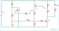
I have this latching circuit diagram which I would like to use to switch power on and off to the rest of the circuit (a 555 and a 4017be IC.)
The latching circuit gets its 'turn on' signal from a mini switch. But where should I connect the mini switch in the latching switch circuit to make the circuit switch on?
The latching switch is suppose to power a 555 and a 4017be decade counter. Where should I connect the vcc or ground from the ICs to the latching circuit switch?
A signal from the decade counter 4017be's output 6 is suppose to turn the latching switch off after only 1 cycle. Where should I connect the output 6 to the latching circuit diagram?
So in general the mini switch turns on power to the main circuit and the 4017 turns it off. Both with help from the latching switch circuit.
Thank you so much in advance.
Attachments
-
 13.2 KB Views: 29


