Facebook
 Google
 GitHub
 Linkedin

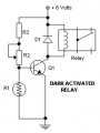
can anyone help me please, i need schematic of the laser tripwire circuit with option for alarm to get ON only when the beam is broken and the 2nd option for alarm to get ON when the laser beam is breached and to stop only when the alarm is reseted?!
I already have the dark activated switch see the photo, i need just to ad the relay switch but i have no idea how...
Thanks
Last edited by a moderator: