laplace transform in RC circuit

Thread Starter

ashmeo

Joined Nov 21, 2011
17
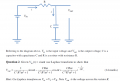
Hi everyone, I've been given a problem and I can't seem to prove it. The picture shows a filter, ( i think its a low pass filter) [pic attached]

Here's what i got so far.

I've got Vr=iR
Vc= Vin(1-e^-t/RC)

Vin=Vr+Vc
= iR + Vin(1-e^-t/RC)
= iR + sinwt(1-e^-t/RC)

since Vr=Vout, and Vin = sinwt

sinwt = Vout + sinwt(1-e^-t/RC)

Vout= sinwt - sinwt(1-e^-t/RC)

am i suppose to laplace this?

If yes,

and when i laplace Vin=Vr+Vc as stated in the hint , i got L{vin} = iR/s + w/(s^2 + w^2) + w/ [ (s+1/RC)^2 +w^2 ]

how am i supposed to continue and relate to proving Vout?

tell me what to do step by step as im still a beginner and thanks for your replies! I appreciate it :)
 

Attachments

t_n_k

Joined Mar 6, 2009
5,455
As I stated to the other member who posted exactly the same question you need to re-cast the circuit in the Laplace domain first and then you solve it. You don't solve the circuit in the time domain first and then re-cast the solution into the Laplace domain.

This is the process one normally follows:-

  1. Draw the schematic in the Laplace domain form.
  2. Using normal methods of circuit solutions [KVL & KCL] derive the required parameter [voltage or current] in the 's' [Laplace] domain form using algebraic manipulation methods consistent with those applied to DC circuit problem solutions.
  3. Simplify the 's' domain parameter form in terms of the typical forms found in standard tables of Laplace domain vs Time domain equivalents.
    [*]Using the standard tables transform the derived 's' parameter back to the equivalent time domain form.
 

Thread Starter

ashmeo

Joined Nov 21, 2011
17
We have not learnt about drawing it in laplace domain form.
But im familiar with kvl kcl.
I have already laplaced the voltages as shown in the first post. How do i continue?
 

WBahn

Joined Mar 31, 2012
30,045
You are also confusing lots of things. In fact, you are pretty much just throwing equations against the wall hoping something will stick.

You state:
Vc= Vin(1-e^-t/RC)
Where is this coming from? Under what conditions is this equation valid? Do those conditional apply in this circuit?

You then say

since Vr=Vout
Why do you think that the output voltage is the same as the voltage across the resistor?

Now look at your result:

Vout= sinwt - sinwt(1-e^-t/RC)
Does this make sense? At t gets large (say more than 5*RC), what does Vout do in this expression? Does this make sense in light of the fact that the source is going to keep driving the circuit for all t>0?
 

WBahn

Joined Mar 31, 2012
30,045
We have not learnt about drawing it in laplace domain form.
But im familiar with kvl kcl.
I have already laplaced the voltages as shown in the first post. How do i continue?
If they haven't taught you how to transform the circuit into an s-domain equivalent, then they are probably expecting you to develop the differential equation that describes the circuit and take the Laplace transform of that.

So:

1) What is the differential equation governing the circuit?

2) What are the initial conditions?

3) What is the Laplace transform of the differential equation?
 

Thread Starter

ashmeo

Joined Nov 21, 2011
17
how do i derive the differential equation?

And the question stated that Vout is the voltage across resistor R.

But since this is a filter, the vout is can be changed according to the inputs or conditions which the question did not specify. So what now? I dont understand.


Which formula do i have to use for the capacitor in this circuit? Help me please I'm kinda lost when it comes to circuit analysis,

Other forums suggested me to use millman's theorem. I have not learnt it. Any alternative?

L {Vin} = L{sinwt}

= w/(s^2+w^2)

And I think the Volatage of capacitor is same as Vout since they are in parallel.

Btw i got the formulae off wikipedia. This is a mathematics module assignment and the circuit theory was not told to us. Thus we have to do our own learning so pardon me if I'm using wrong formulae or making wrong assumptions.

In terms of mathematical calculation and laplace, I;m able to do it. Just need help in terms of the starting so i can prove it.
Thanks for your replies.
 

Attachments

Last edited:

WBahn

Joined Mar 31, 2012
30,045
how do i derive the differential equation?
Let's take it step by step.

1) Assign voltages V_in, V_R and V_C to each component with the polarity consistent with the passive sign convention for the direction of current given on the diagram.

2) For each device, write the relationship between the voltage across the device and the current through the device using that device's characteristic equation.

3) Apply KVL around the loop, being sure to observe the polarities of the assigned voltages.

The result is a differential equation for the current or, depending on how you wrote things, a differential equation for the capacitor voltage (which would actually be preferred since that is what you eventually want, but either will do).

4) What are the initial conditions of the circuit? (At t=0, what is the voltage on the capacitor?)

Let's get this far and then proceed from there.

And the question stated that Vout is the voltage across resistor R.
I couldn't for the life of me figure out where you are getting this notion. I read the problem several times and looked at the figure very closely. Then I looked at the hint and now I see where you are getting this from. The last sentence in the hint and the circuit given don't match. The Vout given in the circuit is the voltage between the top right node (the junction of the R and C) and ground. Is this the voltage across R? No. It is the voltage across C.

Now, either the hint is correct or the diagram is correct. As a rule, the diagram and problem statement take precedent over a hint, but that doesn't mean that the author didn't work the problem assuming their hint was correct and that the answer matches the hint. In this case, however, the given equation that you are trying to show is the equation for the voltage across the capacitor.

Now, the diagram does not specify the assigned polarity of Vout, which is sloppy of the author. But it's not the only thing they were sloppy about. Fortunately, nearly universal and natural convention assigns the polarity to be positive if the RC junction is at a higher voltage than ground.

But since this is a filter, the vout is can be changed according to the inputs or conditions which the question did not specify. So what now? I dont understand.
Forget about whether it is a filter or not. It is a circuit having a defined voltage applied to two series components and you are to determine the voltage across one of them. Don't make it harder than it is.

Which formula do i have to use for the capacitor in this circuit? Help me please I'm kinda lost when it comes to circuit analysis,
What is the fundamental relationship between the voltage on a capacitor and the current through it?

Other forums suggested me to use millman's theorem. I have not learnt it. Any alternative?
Stick with the fundamentals. Millman's theorem can be applied here, but it is needlessly complicated for such a special simplified case and will merely yield the same result that direct application of KVL will yield.
 

Thread Starter

ashmeo

Joined Nov 21, 2011
17
i(C) = C dv/dt ??

At t=0 the capacitor is initially uncharged. thus Vc=0V?


Vo= Vr + Vc
= iR + 1/C * (integrate 0-t) {i}
 

WBahn

Joined Mar 31, 2012
30,045
i(C) = C dv/dt ??

At t=0 the capacitor is initially uncharged. thus Vc=0V?
Yes. The fundamental equation for an ideal capacitor is

Q = CV

From this we can go in either of two directions:

\(
i_C(t)\;=\;\frac{dQ(t)}{dt}\;=\;C\frac{dv_C(t)}{dt}
\)

or

\(
v_C(t)\;=\;\frac{1}{C}Q(t)\;=\;\frac{1}{C}\int_0^t i_C(t)\;+\;v_C(t=0)
\)

Vo= Vr + Vc
= iR + 1/C * (integrate 0-t) {i}
What is Vo?
 

WBahn

Joined Mar 31, 2012
30,045
Sorry i meant Vin.
Okay, so you basically have, at this point:

\(
v_{in}(t)\;=\;i(t)R\;+\;\frac{1}{C}\int_0^t i(t)\;+\;v_C(t=0)
\)

Which is a perfectly good differential equation in terms of the circuit current. You can then use Laplace transforms to transform it into the Laplace domain, solve it, and transform back to get the time domain current. Once you have that, getting the voltage across the capacitor (namely Vout) is straightforward since you know that

\(
v_{out}(t)\;=\;v_{in}(t)\;-\;i(t)R
\)

But another way is to develop the differential equation for the voltage across the capacitor, instead of the circuit current, since that is ultimately what you want. So you have:

\(
v_{in}(t)\;=\;v_R(t)\;+\;v_C(t)
\
v_{in}(t)\;=\;i(t)R\;+\;v_C(t)
\)

But since the current in the resistor is the current in capacitor, we can use our equations for the capacitor to write the resistor current in terms of the capacitor voltage:

\(
i\;=\;i_C(t)\;=\;C\frac{dv_C(t)}{dt}
\)

thus

\(
v_{in}(t)\;=\;RC\frac{dv_{out}(t)}{dt}\;+\;v_{out}(t)
\)

Where I have also used the fact that v_c = v_out.

You can solve either of these differential equations; in fact, I strongly recommend that you solve the problem both ways to get a feel for how much effort can be saved by choosing some of your options wisely as you go. But it is also good practice and it also shows that if you can arrive at the same solution multiple ways, then you can also use that ability to check your answers against each other to catch mistakes.

At this point I want to make note of some more sloppiness on the author's part (and a very common one). The author says that

\(
V_{in}\;=\;\sin(\omega t)
\)

First, this is simply nonsensical since Vin is a voltage and sin(anything) is a dimensionless number. So this should have been given as

\(
V_{in}\;=\;1V\sin(\omega t)
\)

I personally tend to abstract it one more step and make it

\(
V_{in}\;=\;V_0\sin(\omega t)\; ;\; V_0=1V
\)

By working as symbolically as possible for as long as possible, it let's you see the underlying structure of the method and the result, makes it easy to generalize the result to arbitrary parametric variations, and let's you catch and correct mistakes much more easily.

The other sloppiness commited by the author is to assume that the reader understands that it it implied that the input voltage is equal to the given expression starting at t=0s and that it was identically equal to zero before that. A correct way to express this would be

\(
V_{in}\;=\;V_0\sin(\omega t)u(t)\; ;\; V_0=1V
\)

where u(t) is the Heaviside step function that is 0 for t<0 and 1 for t>=0. Hopefully you are already familiar with this notion.

So, using the second form of our differential equation (the one in terms of capacitor voltage), what is the Laplace transform of it term-by-term?
 

Thread Starter

ashmeo

Joined Nov 21, 2011
17
Thanks man! You have been really helpful. I'll try it and get back to you soon. Thanks again.

EDIT: Hey! I chose to do the second method first. So far here is what i got.

Vout= sinwt -RC dv/dt
L{Vout} = w/(s^2+w^2) - RCsV since v(0) =0.

do i cross multiply? How would i use partial fractions then?


If i use the first method, Vin= iR +1/C int 0-t i dt + v(0)

L{Vin} = IR + I / (Cs) + 0 <--- is this right?
 
Last edited:
Top