Facebook
 Google
 GitHub
 Linkedin
hello everyone
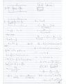
I do this problem on Laplace circuit
please see my solution true?
thanks
I do this problem on Laplace circuit
please see my solution true?
thanks
Attachments
-
 33.1 KB Views: 105
 -
 431.4 KB Views: 84
")