Lamp Repair

Thread Starter

LED Man

Joined Jan 15, 2008
62
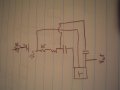
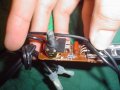
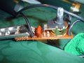
Hey guys, I'm trying to repair a lamp and had some questions. I've attached a pic of the lamp and the pcb.

Basically the wiper in the pot is busted and not making a clean connection, so the light goes on and off and from dim to really bright sporadically.

So, it's either I replace the old pot on the board or I just design another board in place of the one already there. I'd like to design a new board in place of that one but don't really have experience designing a circuit.

I assume there is a 12v 120ac signal coming which I input to the pot, but then it looks like there are 2 caps and a resistor in parallel with the pot? It also looks like a voltage regulator is on there? Or is that a transistor? The part number on it says BTA12 400C C514.

Any help is appreciated, thanks guys.
 

Attachments

I just read this a couple of days ago and found it interesting. No circuit design but a simple explanation of a dimmer switch...

home.howstuffworks.com/dimmer-switch.htm

S@H
 

Thread Starter

LED Man

Joined Jan 15, 2008
62
Awesome thanks for all the info.

Am I right in saying that the current circuit has an interference capacitor? I see one larger cap and one really small cap that is blue. I think I will redesign the circuit to incorporate the inductor choke because I remember noticing a significant buzz when the lamp was working. Also, I think I'm going to go off the circuit they have on this site http://home.howstuffworks.com/dimmer-switch4.htm. However I notice an extra resistor in the current circuit for the lamp, is that put in parallel to decrease the voltage drop?

Also, is there anyway I can find and verify the right values for the components I'll need to buy? I know the triac but the caps I'm not sure. Also, is that long metal piece coming off the triac for heat dispersion? Not really sure what it's there for. Thanks guys.
 
Is this diagram from the circuit you pulled out of the lamp?

The diagram doesn't match the one from the website. If you take out the inductor, the Vin has three connections (CAP, RES, TRIAC) and the Vout has three connections (CAP, CAP, TRIAC). As far as component selection, I would try to identify the components on the current board and start there. I myself just went to the hardware store and bought another dimmer, so my experience ended with the website.
 

Thread Starter

LED Man

Joined Jan 15, 2008
62
I actually tried drawing up the schematic from the current board for the lamp.

The other thing I guess I could do is just replace the pot. I'm not sure what type of pot it is and I don't have a DMM.

Does anyone recognize what type of pot that is?
 

Thread Starter

LED Man

Joined Jan 15, 2008
62
Nope, there is nothing written on the pot.

Also, if I want to just replace the component, does anyone know of a way to remove solder without one of those solder suckers? All I have at the moment in a soldering iron. I feel like the easiest thing would just be to buy another pot and replace the one on there.
 
You can get a copper braid that will wick up the solder after it is heated. It is sometimes referred to as Solder Wick or desoldering braid. It used to be available at Radio Shack.
 

Thread Starter

LED Man

Joined Jan 15, 2008
62
Hey thanks. I actually was just able to remove it. Now I just need to find a replacement. There are no part numbers anywhere on the pot. Do you recognize it from the pics I posted? I can post some more pics of the pot if you want. Thanks.
 

bertus

Joined Apr 5, 2008
22,276
Hello,

It looks like this schematic:


In your drawing you have drawn 2 capacitors, I think one of them is the diac.
Can you read the values of the capacitor?
The RC time is max 1/2 cycle (8.33 mSec for 60 Hz and 10 mSec for 50 Hz).

Greetings,
Bertus
 

Attachments

Thread Starter

LED Man

Joined Jan 15, 2008
62
Thanks so much!
The diac has a "30" on it.
The cap looks like is says "333K 409V"
The resistor is "Gold, Orange, Black, Brown"

So I would basically input this circuit right in the positive AC main coming in?

The ground wire is not interrupted at all throughout the lamp.

Lastly, the inductor is right before the output to the bulb right? Thanks.
 

bertus

Joined Apr 5, 2008
22,276
Hello,

The drawn coil is the load , in your case the lamp.
The capacitor is 333K , that says 33 nF / 400 Volts.
The resistor is "brown black orange gold" , that says 10 KOhm , 5 %
The 30 on the diac is probably the trip voltage.

The potmeter will probably be in the range of 250 KOhm.

Greetings,
Bertus
 

Thread Starter

LED Man

Joined Jan 15, 2008
62
Hey guys, I know it's been a while but I just picked this up:
http://www.radioshack.com/product/i...duxyeVQEwyZcBGg&productId=3012598&tab=support

Do you think it will work? Also, I know terminals 2 and 3 are for the output of the pot, but what are the contacts for under the actual wiper? There are three contacts and not exactly sure what they are. In my previous posts on this thread I have a photo of the circuit board and there are inputs on the pcb that are perpendicular to each other. Now, I have to figure out how to input this new pot in the old terminal location. Thanks.
 
Top