 Facebook
 Google
 GitHub
 Linkedin
Hello, everyone!
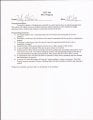
It has been awhile since I was last in this forum. At my school, we began to focus on industrial electronics and PLCs. In this, we need to become familiar with ladder diagrams and such. For one of the Lab assignments that my teacher gave us, I am having some trouble getting the ladder diagram made for the PLC program (RSLogix 5000). I was wondering if anyone was familiar with this and would help me out.
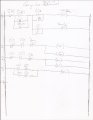
Attached are some pictures of my work as well as the requirements for the diagram/program. Lately, I've been feeling very stressed and anxious, and it causing me not to think straight. Rungs 0 through 2 are correct, and I feel Rung 3 is correct as well. I mean, we have door a simple garage door before on a Motion Control System, so I have the base of this project figured out.
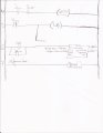
Rungs 4 and 5 are for the "Don't kill Timmy" circuit as described in the requirements. That portion of it completely confuses me, and I don't understand how I even get the ladder logic set up for it.
Rungs 6 and 7 are for the Maintenance Timer. Since I couldn't stay in the lab later than normal (due to work that day), I wasn't able to test these out. In my opinion, it looks like it's right, but I'm not too sure.
To everyone that responds, thank you so much for helping me out. If this isn't the correct subforum, I'll be more than happy with moving the thread.
It has been awhile since I was last in this forum. At my school, we began to focus on industrial electronics and PLCs. In this, we need to become familiar with ladder diagrams and such. For one of the Lab assignments that my teacher gave us, I am having some trouble getting the ladder diagram made for the PLC program (RSLogix 5000). I was wondering if anyone was familiar with this and would help me out.
Attached are some pictures of my work as well as the requirements for the diagram/program. Lately, I've been feeling very stressed and anxious, and it causing me not to think straight. Rungs 0 through 2 are correct, and I feel Rung 3 is correct as well. I mean, we have door a simple garage door before on a Motion Control System, so I have the base of this project figured out.
Rungs 4 and 5 are for the "Don't kill Timmy" circuit as described in the requirements. That portion of it completely confuses me, and I don't understand how I even get the ladder logic set up for it.
Rungs 6 and 7 are for the Maintenance Timer. Since I couldn't stay in the lab later than normal (due to work that day), I wasn't able to test these out. In my opinion, it looks like it's right, but I'm not too sure.
To everyone that responds, thank you so much for helping me out. If this isn't the correct subforum, I'll be more than happy with moving the thread.
Attachments
-
 563.1 KB Views: 49
 -
 380.2 KB Views: 48
 -
 344.9 KB Views: 44


