 Facebook
 Google
 GitHub
 Linkedin
Newbie question....
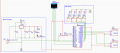
I have a very simple circuit in which an ESP32 drives 2 servos. It's powered by a 9V AC/DC power supply that runs through a voltage regulator. I measured the circuit's current, and it doesn't go above 800mA as the ESP32 logic ensures the servos never run simultaneously. The circuit is something like this:

My question is:
With the L7805, the servos refuse to work and the ESP32 frequently resets.
When I use the ASM1117 it works fine.
The only thing I can think of is that the power supply doesn't provide enough current BUT looking at this site and the data sheets, the L7805 should provide more current (up to 1-1.5A) compared to the ASM1117 (800mA).
So could someone explain why this circuit does not work with the L7805?
Thanks in advance
I have a very simple circuit in which an ESP32 drives 2 servos. It's powered by a 9V AC/DC power supply that runs through a voltage regulator. I measured the circuit's current, and it doesn't go above 800mA as the ESP32 logic ensures the servos never run simultaneously. The circuit is something like this:
My question is:
With the L7805, the servos refuse to work and the ESP32 frequently resets.
When I use the ASM1117 it works fine.
The only thing I can think of is that the power supply doesn't provide enough current BUT looking at this site and the data sheets, the L7805 should provide more current (up to 1-1.5A) compared to the ASM1117 (800mA).
So could someone explain why this circuit does not work with the L7805?
Thanks in advance
Attachments
-
 190.4 KB Views: 6


