Kirchoff's 2nd law related problem.

Thread Starter

TwoPlusTwo

Joined Oct 14, 2010
51
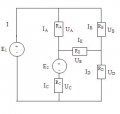
We've been given the circuit below, and have measured the current through and voltage across each resistive element. The voltages of E1 and E2 are set to 10 V and 15 V, respectively.

Now we are asked to calculate a new value for E2 that will make IE=0.

What's the general approach here?

Should we consider E2, RE, RD and RC as a closed network (as formulated by Kirchoff's 2nd law), or do we also have to consider the effect from E1?

Any help would be much appreciated!
 

Attachments

Thread Starter

TwoPlusTwo

Joined Oct 14, 2010
51
Ok.Thanks! And as I adjust E2 up or down, the algebraic sum of voltages around the loop will remain zero, and the voltage across the resistive elements will be proportional to their resistance level? Is this correct?
 

Georacer

Joined Nov 25, 2009
5,182
It is proportional, as V=I*R, but not to each other too, because a different current I runs through Rc and Rd. Don't try to put it on a logical basis right now. Just use your equations to come to a correct result and try to see later the big picture behind it.
 

Adjuster

Joined Dec 26, 2010
2,148
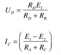
Since you require IE=0, begin by evaluating UD given this condition. This can be found by potential division from E1, RB and RD.

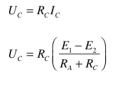
Now, how to write an equation for UC+E2? In the eventual solution IE=0, so only E1, E2, RA and RC need be considered. Evaluate the current down the branch assuming IE=0, and hence find UC.

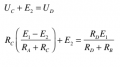
Equating the expressions for UD and UC+E2 will give the required result.
 

Thread Starter

TwoPlusTwo

Joined Oct 14, 2010
51
Since you require IE=0, begin by evaluating UD given this condition. This can be found by potential division from E1, RB and RD.

Now, how to write an equation for UC+E2? In the eventual solution IE=0, so only E1, E2, RA and RC need be considered. Evaluate the current down the branch assuming IE=0, and hence find UC.

Equating the expressions for UD and UC+E2 will give the required result.

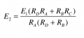
Thanks, Adjuster! I've tried to follow your approach. How does it look? Not a hundred per cent sure I got this right...
 

Attachments

Adjuster

Joined Dec 26, 2010
2,148
There must be something wrong. The expression should have dimensions of voltage, but it has dimensions of current (E/R).

Also, depending on the resistance values, E2 may need to be negative or positive. Your expression does not show that.

Look carefully over your working, see if you can find a mistake somewhere
 

Thread Starter

TwoPlusTwo

Joined Oct 14, 2010
51
I worked through it one more time, and I can't find anything wrong with the algebra. Are you sure this can't be right? Maybe the expressions I started out with are wrong?
 

Adjuster

Joined Dec 26, 2010
2,148
You started with expressions all in dimensions of voltage: I've written them differently so we can see that better.

(E1-E2)*RC/(RA+RC) + E2 = E1*RD/(RB+RD)

Your final expression should also be dimensionally correct for a voltage.

It should contain subtracted terms.

E1*RC/(RA+RC) -E2*RC/(RA+RC)+ E2 = E1*RD/(RB+RD)

-E2*RC/(RA+RC)+ E2 = E1*RD/(RB+RD) -E1*RC/(RA+RC)

E2*(RA)/(RA+RC) = E1*RD/(RB+RD) -E1*RC/(RA+RC)

I wonder if I have that right so far - it is very late now. For you to check and carry on to simplify.
 

Thread Starter

TwoPlusTwo

Joined Oct 14, 2010
51
I belive all your steps are correct so far, but I think you will still end up with the same expression as I got.

Wolfram Alpha agrees:

Link

Note that I shortened RC to C, RA to A and so on, to make it easier for the program to read. E1 is now just E and E2 is x.

Inputting the last step in your calculations gives the same result:

Link

So if you are positive it can't be right, then there must be something wrong with how I set up the expressions in the first place.
 

Adjuster

Joined Dec 26, 2010
2,148
I belive all your steps are correct so far, but I think you will still end up with the same expression as I got.

Wolfram Alpha agrees:

Link

Note that I shortened RC to C, RA to A and so on, to make it easier for the program to read. E1 is now just E and E2 is x.

Inputting the last step in your calculations gives the same result:

Link

So if you are positive it can't be right, then there must be something wrong with how I set up the expressions in the first place.
I am sorry to have to admit that I was wrong about the dimensions For this I must apologise. I should not really have tried to answer so late last night. What still seems strange is that there is no subtraction in your answer.

Why not try putting your results from the experiment into your formula,to see if it gives a reasonable result?
 

Thread Starter

TwoPlusTwo

Joined Oct 14, 2010
51
I am sorry to have to admit that I was wrong about the dimensions For this I must apologise. I should not really have tried to answer so late last night. What still seems strange is that there is no subtraction in your answer.

Why not try putting your results from the experiment into your formula,to see if it gives a reasonable result?
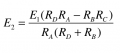
You're absolutely right about the subtraction! Notice that the the solution in wolfram is identical to mine expect for the minus sign in the numerator. The correct solution should be as below.
 

Attachments

Thread Starter

TwoPlusTwo

Joined Oct 14, 2010
51
The approximate values we measured in the lab were as follows (not entirely sure if they were measured correctly...):

RA=175, RB=700, RC=850, RD=100 (all in Ohm)

E1=10V

When I plug these values into my equation I get

E2= - 36.7 V

I'm not qualified to determine if that seems reasonable ;)
 

Jony130

Joined Feb 17, 2009
5,599
Very strange, so maybe we try so different approach
For
RA=175, RB=700, RC=850, RD=100
E1=10V

Ud = 10V * 100/800 = 1.25V

So we need E2 + UC = 1.25V
So form KVL
10V = 1.25V + Ia*175Ω ---> Ia = 0.05A = 50mA

Uc = Ia*Rc = 42.5V

1.25V = E2 + 42.5V ---> E2 = -41.25V
 
Top