Karrimor Pace Treadmill - No error codes, motor stalling

Thread Starter

Dean.

Joined Nov 5, 2025
11
Hi All,
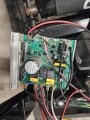
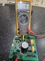
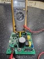
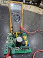
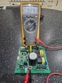
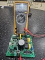
I have a Karrimor Pace treadmill which until recently worked fine. Now however the belt does not turn.
I have no error codes and the display assumes all is ok, the speed indicator/display goes up and down and the incline works fine.
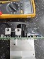
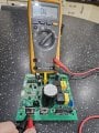
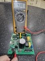
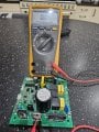
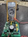
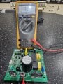
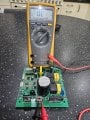
I have bridged the motor wires and the resistance increases when manually pushing the belt so assume the motor is ok. I have checked the ohms on the speed sensor and it fluctuates when rotating so again assume this is ok. I have power to the board too.
I can hear a high pitched whine from the motor like is stalling but you can see it moving slowly regardless of the speed adjustment.
I am assuming this may be a power/control board issue but before spending £80 do any of you have any suggestions?
Thank you
Dean
 

MaxHeadRoom

Joined Jul 18, 2013
30,609
Not familiar with that make, but test the motor on a DC supply, i.e., an automotive battery, etc.
If OK, most likely something in the motor control circuit may require some reverse-engineering!
Post a pic of the board.
 

Thread Starter

Dean.

Joined Nov 5, 2025
11
Not familiar with that make, but test the motor on a DC supply, i.e., an automotive battery, etc.
If OK, most likely something in the motor control circuit may require some reverse-engineering!
Post a pic of the board.
I will try and run it up shortly 9ff a battery. Circuit board picture attached.
 

Attachments

Rockettfuel

Joined Sep 17, 2025
29
From the perspective of the board in the image everything looks ok.
It may be an output voltage/current issue from the board to the motor.
Are you comfortable testing the live DC voltage output wires to the motor?

PLEASE USE CAUTION WHEN USING THIS METHOD
I would disconnect the DC voltage output wires from the motor
and use your DMM to connect to those - and + output wires.
Keep in mind the board's capacitors may still have
voltage stored inside.

(LIVE VOLTAGE)
Next I would turn on the treadmill and start at the lowest speed and
gradually increase speed. The voltage reading on your DMM should increase
as you increase the speed of the treadmill. If the voltage reading does
not increase with the treadmill speed, then your board is not outputting
proper voltage/current.

If youre not comfortable testing the live DC voltage then I would test
the MOSFETs. That's my first assumption that the board's MOSFET
are failing to opening. I would test the MOSFET and that approach
depends if they are N or P channel.
Do you hear the relays click before the motor starts?
 

MaxHeadRoom

Joined Jul 18, 2013
30,609
The principle culprits on TM controllers like this, is the motor Mosfet mounted on the HS. Check it, and also trace if it has processor controlled
 

Thread Starter

Dean.

Joined Nov 5, 2025
11
From the perspective of the board in the image everything looks ok.
It may be an output voltage/current issue from the board to the motor.
Are you comfortable testing the live DC voltage output wires to the motor?

PLEASE USE CAUTION WHEN USING THIS METHOD
I would disconnect the DC voltage output wires from the motor
and use your DMM to connect to those - and + output wires.
Keep in mind the board's capacitors may still have
voltage stored inside.

(LIVE VOLTAGE)
Next I would turn on the treadmill and start at the lowest speed and
gradually increase speed. The voltage reading on your DMM should increase
as you increase the speed of the treadmill. If the voltage reading does
not increase with the treadmill speed, then your board is not outputting
proper voltage/current.

If youre not comfortable testing the live DC voltage then I would test
the MOSFETs. That's my first assumption that the board's MOSFET
are failing to opening. I would test the MOSFET and that approach
depends if they are N or P channel.
Do you hear the relays click before the motor starts?
No voltage output fluctuations when measured in DC at the motor, it does click when turned on.

I now have removed the circuit board fully and have the attached picture, im guessing these are what I need to test next?
 

Attachments

Thread Starter

Dean.

Joined Nov 5, 2025
11
No voltage output fluctuations when measured in DC at the motor, it does click when turned on.

I now have removed the circuit board fully and have the attached picture, im guessing these are what I need to test next?
Test on first component shown in pictures. Left and right pins make DMM bleep.
 

Attachments

Rockettfuel

Joined Sep 17, 2025
29
Ok, So your voltage reading increases when you increase the speed
of the treadmill. Which means the control signal from the board
and command from the treadmill console is responding.
I believe at low speeds you should see around 30V and high speeds
around 180V.
Also the clicking sound you're hearing means
the relays are receiving voltage signal and thats good.

Now the issue could be that not enough current
is being supplied to turn the motor under load.

Testing the MOSFETS,
lookup the part number on the front of the mosfet to confirm
if you have a N-channel or P-channel mosfet. Its super important
for testing. I'll assume you have N-channel so I'll proceed as such.

High-side mosfet is the one closest to that massive capacitor.
Low-side mosfet is the one closer to the motor connectors
on the board.

I agree with MaxHeadRoom on the highside mosfet possibly
causing the issue.
Can you solder and desolder?
To get a good reading its best to desolder the high-side mosfet
from the board. When looking at the front of the mosfet, the
leads from left to right are Gate, Drain, Source.
Once removed take your DMM and put it in diode mode, place your
red probe on Source and black on Drain.
The DMM should read 0.4V - 0.6V.
Reverse the probes and your DMM should read OL, red on Drain
black on Source.
This means Mosfet is good.

If you get OL or ~0V both ways then Mosfet is bad.

If high-side mosfet is bad then as a precation replace the
low-side mosfet also. If high-side is good then conduct
the same test on the low-side to determine its state.

One helpful tip I learned is you test what you know. If you're not sure
or want to confirm, always check with the component's datasheet.

Desoldering you need a soldering iron, flux, leaded soldering
wire w/flux core, soldering wick or desoldering pump.
And you'll need to apply thermal paste when reinstalling the heatsink on
the Mosfets.
Pardon me if you aleady have experience Desoldering/Soldering.
 

MaxHeadRoom

Joined Jul 18, 2013
30,609
No voltage output fluctuations when measured in DC at the motor, it does click when turned on.

I now have removed the circuit board fully and have the attached picture, im guessing these are what I need to test next?
Post #9, The RH component is the bridge rectifier, you should normally have full DC ~120v when powered, the other two normally are the MOSFET and rectifier , best to remove them for testing, use short circuit position to test on the meter you show.
 

Thread Starter

Dean.

Joined Nov 5, 2025
11
Hi, I am buying the components to repair this and have located the first 2 on ebay (see attached) but I cannot find the MHCXHM SFP3060 anywhere.
I wamt to change all three as per the advice but cannot find this or any equivalent, the only one I found was MUR3060PTH-BP (MCC) but not sure at all if its compatible.
Any chance of some help please?
 

Attachments

twohats

Joined Oct 28, 2015
609
Hi,
It's not usually a good idea to replace components unless they have failed.
Your indicated new components are unlikely to be as good as the originals.
Cleaning the board both sides with a stiff paint brush will not do any harm.
Damp dust can and will conduct. I can see it's dry at the moment.
(The above are just my thoughts).
Please keep us informed of your progress.
Good luck..........
 
Top