Facebook
 Google
 GitHub
 Linkedin
Hi guys...
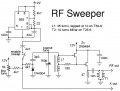
In the diagram shows a common impedance coupling between the RF amplifier composed of T2 and mixer the there are two resonant circuits L2 //C2 and L3//C3 which are not directly coupled but coupled via an inductor L4 which controls the bandwidth.
By introducing the controlled soft grounding of the common reference terminal through L4, the coupling coefficient across the circuit involving T2 can be very carefully controlled by component value. That makes a much more predictable VHF passband.The difference current between L2 and L3 flows in L4 and it is this difference current is effectively doing the mutual coupling. The bandwidth of the RF amplifier needs to cover the whole VHF TV band as it is not tuned with channel changes. The coupling coefficient needs to remain reasonably constant over the entire band.
The coupling coefficient k = Lm + M / √(Lp + Lm)(Ls + Lm) —————————————1
VHF passband = 90 - 100 MHz
XC2 = 300 Ω // reactance of C2
XC3 = 600 Ω // reactance of C3
Q = 10
M = 1
XL4 = 42 Ω // reactance of L4
Coupling coefficient k should remains constant throughout the whole passband of 20 Hz as described but if I substitute above values in equation 1. it would provide me different values of k for the entire passband. Then how can I seem to validate the text above…??