Facebook
 Google
 GitHub
 Linkedin
Hi,
I'm having a bit of trouble with a discontinued product and the organization is not being helpful and doesn't have a manual available. The product is a DEFY g5 camera gimbal. It has a joystick that controls the motor. The joystick broken when the cable was pulled out of its chassis.
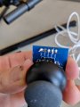
This product is unique in that the joystick circuit board NEEDS to connect into the motor control's circuitry using a 3-ring headphone jack for some odd reason.
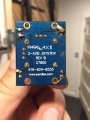
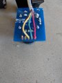
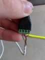
When the jack was pulled from the joystick's circuit board (a parallax 2-axis board), the wiring remnants were very messy and the solder points were very odd, so I went and purchased a new 2-axis (adafruit) joystick that had very simplistic holes that I could solder onto,(x,y,pwer,ground and a select button that is not being used - you push the joystick down to activate, something the old one never used). I also purchased a new headphone jack that had screw-in contact terminals, as it makes the job a lot easier to troubleshoot and the previous headphone jack would have been a little short now.
After cutting a length of quad wire and soldering into the joystick board and attaching the other wire ends to the screw in headphone jack terminals, I get absolutely nothing. I'm starting to wonder if there is any way that the joystick can determine what is up vs down or left vs right on each axis, and if there is some sort of additional wiring that I need to add to accomplish this.
Alternatively, if anyone knows an easier way to get a properly working controller, keeping in mind of the unusual 1/8" headphone jack input, I'm all ears.
Thanks for your help.
Colin
I'm having a bit of trouble with a discontinued product and the organization is not being helpful and doesn't have a manual available. The product is a DEFY g5 camera gimbal. It has a joystick that controls the motor. The joystick broken when the cable was pulled out of its chassis.
This product is unique in that the joystick circuit board NEEDS to connect into the motor control's circuitry using a 3-ring headphone jack for some odd reason.
When the jack was pulled from the joystick's circuit board (a parallax 2-axis board), the wiring remnants were very messy and the solder points were very odd, so I went and purchased a new 2-axis (adafruit) joystick that had very simplistic holes that I could solder onto,(x,y,pwer,ground and a select button that is not being used - you push the joystick down to activate, something the old one never used). I also purchased a new headphone jack that had screw-in contact terminals, as it makes the job a lot easier to troubleshoot and the previous headphone jack would have been a little short now.
After cutting a length of quad wire and soldering into the joystick board and attaching the other wire ends to the screw in headphone jack terminals, I get absolutely nothing. I'm starting to wonder if there is any way that the joystick can determine what is up vs down or left vs right on each axis, and if there is some sort of additional wiring that I need to add to accomplish this.
Alternatively, if anyone knows an easier way to get a properly working controller, keeping in mind of the unusual 1/8" headphone jack input, I'm all ears.
Thanks for your help.
Colin
Attachments
-
 182.2 KB Views: 7
 -
 116.6 KB Views: 7
 -
 182.2 KB Views: 7
 -
 86.5 KB Views: 7