How to use a old joystick of a drone controller

Thread Starter

FelixB

Joined Dec 26, 2022
33
Hello everyone,
two days ago I got a new soldering-station and equipment for it, so I thought I can dig up the old electronic case to utilize it.
I found a nice drone controller (YD-829) which i thought I could use perfectly for a small Raspberry Pi Pico RC Car/Robot. The Problem is:
I don't now how to wire up the two joysticks to work with my Pico.

IMG_7049.jpg
IMG_7051.jpg
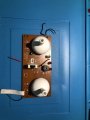
The two arrows mark the Joysticks on the back

There are, how it seems to me, six pins for the joystick. Three for X-Axis and three for Y-Axis.
I dont think the four pins at the corners are having any use, despite holding the joystick in place. My thoughts on that are, that each Axis has one Power-Pin, one GND-Pin and one ADC-Pin.
But is there a way to figure out which Pin is which?
I don't wanna test it with my Pico (once I accidently wired GND and Power the wrong way and broke my Pico).
Is my assumption of the six Pins even right?

I'm exited to hear your thoughts on that and be thankful in advance!
 

Attachments

MrChips

Joined Oct 2, 2009
34,628
Welcome to AAC!

The four pins in the corners are for securing the joystick to the PCB.
The two groups of three pins are connections to a potentiometer (pot for short) or variable resistor.
The centre connection is the wiper arm. The two outer pins connect to the two ends of the fixed resistor.

1672067197837.png
 

Thread Starter

FelixB

Joined Dec 26, 2022
33
Thank you for the welcome and the answer @MrChips!

But I am worried that I have another question now:
When they are just representing the Terminals TO a potentiometer, can I even use them for my project?
OR
How, if possible, can I get the ADC data of the potentiometer?
 

MrChips

Joined Oct 2, 2009
34,628
Thank you for the welcome and the answer @MrChips!

But I am worried that I have another question now:
When they are just representing the Terminals TO a potentiometer, can I even use them for my project?
OR
How, if possible, can I get the ADC data of the potentiometer?
You can connect the resistor ends to power and ground as you originally suspected with the centre pin going to the ADC input.
Make sure that the positive power is in the same range or lower than the ADC max input.
 

Thread Starter

FelixB

Joined Dec 26, 2022
33
Thank you!
Is there a way to see which outer Pin is power and which is ground? And
I unfortunally don't have the orignal accumulator for the control. Can I somehow see or calculate the voltage required for the joystick to properly function or can I just go with the typicall 3.3 - 5V?
 

MrChips

Joined Oct 2, 2009
34,628
One end of the resistor should go to 3.3V and the other to GND.

1672077280592.png

There is no harm done if you get it wrong. Simply reverse the connections to suit what you want to be UP/DOWN and LEFT/RIGHT.
 

KeithWalker

Joined Jul 10, 2017
3,603
In the diagram of the underside of the circuit board, I can see on the stick on the right, one pin of each axis potentiometer is connected to the ground plane.That will be the negative supply connection The moving contact will be the center of the three pins and the the positive connected to the third pin. I guess the stick on the left looks similar. I assume that you will not be using the rest of the circuit on the board so cut the traces to the center pain and positive pin so that the components on the board do not interfere with the operation.
 

MisterBill2

Joined Jan 23, 2018
27,181
To make an accurate determination as to which pin is what, if you have no device data at all, an ohm meter function will be the simplest method that risks no damage to anything. But you do need to understand how to use the meter to measure resistance.
Unfortunately I have no information about the TS technical skill or understanding skill level
 

Thread Starter

FelixB

Joined Dec 26, 2022
33
Sry for beeing gone for so long I just had lots of work to do. But now I'm back and can write what I did:
  • First I started by unsoldering the Joysticks of the board
  • After that I soldered header pins onto the Joysticks
Img:
IMG_7086.jpg
  • Then i did some testing
Img:
IMG_7087.jpg
IMG_7088.jpg
  • Then I wired one Joystick on to the pico (The Pico only has 3 ADC converters so I couldn't use both of the Joystick)
Img:
Screenshot_20221231_183341.png
Result:
It worked exactly how I wanted it to work.
I used a PS2Controller befor that project but I have to say that I didn't really know how it worked. Thanks to this little project I now know how it works. A Joystick is nothing more then a adjustable resistor and the ADC Pins on the Pico just return the current voltage.
Thank you all for the help!
 

Thread Starter

FelixB

Joined Dec 26, 2022
33
Thanks for the compliment!
I just thought that for the help I received I atleast could do some "documentation" for you guys and make it easier if someone in the future wants to do something like this.
p.s.
I think I will use a external ADC for my wireless controlled robot/car to use the four values of the two Joysticks.
 

KeithWalker

Joined Jul 10, 2017
3,603
I think I will use a external ADC for my wireless controlled robot/car to use the four values of the two Joysticks.
There is an easier solution. You could use a DPDT small 5V relay or a 4 way digital switch (CD74HC4316E) to connect the sliders of each stick to the two analog inputs and use a digital outputs to activate it and sample each stick in turn.
 

darren32

Joined Jan 7, 2023
1
I tried to solder my own but something doesn't work out, probably some defective soldering iron because it doesn't melt at all, you will have to buy a new one and try again
 

MisterBill2

Joined Jan 23, 2018
27,181
It may also be that you have some of that lead free solder, which has a higher melting point than our favorite kind of tin-lead solder. It requires a hotter iron.
 
Top