JFET amplifier problem

Thread Starter

PsySc0rpi0n

Joined Mar 4, 2014
1,762
I have this new problem to solve.

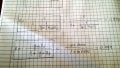
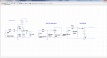
The attached circuit is an amplifier with a JFET!

We are asked to find Av, Ri and Ro for that circuit with gm = 10mA/V and Rd = ∞ (I think Rd is the same as 1/hoe).

First step is to identify the type of amplifier! I would say that this is a common-source amplifier but I'm not sure!
 

Attachments

kyka

Joined Jun 7, 2015
24
No, it is not common-source, it is common-drain (the input is being applied in the gate and the output is being taken from the source).

With some fast approximate calculations, it turns out that

Av=0.94, because it is a common-drain topology and there is a resistor divider at the input
Ri=180 kOhm, because it is a JFet
Ro=500 Ohm because the source resistance is much smaller than the 10k resistance. In absence, of the 10k resistor the Ro would be 1/gm.
 

Thread Starter

PsySc0rpi0n

Joined Mar 4, 2014
1,762
kyka, and can you tell me about if my equivalent small AC circuit and hybrid model are correct? And also how to identify common-drain/source/gate amplifiers?
 
Last edited:

Thread Starter

PsySc0rpi0n

Joined Mar 4, 2014
1,762
With the hybrid model I have that I hope is correct (please anyone confirm it with the screens attached at 1st post), I was trying to calculate the voltage gain but I'm not quite sure how to do it:

Av = Vout/Vin

Vout = gm*Rs//Rload <-- Is this correct?

For Vin, has Ig = 0 I would say that would be:
Vin = (Rg1//Rg2*Vsig)/(Rsig + Rg1//Rg2)

But I don't know Vsig so I can't calculate Av.
 

Thread Starter

PsySc0rpi0n

Joined Mar 4, 2014
1,762
After reading and looking for those schematics in that link, I can't understand what is done for Vout.

For Vout I was multiplying the current gm*Vgs*(Rs//Rload). Wouldn't this be the voltage drop at that parallel that would also be the voltage drop at R_load?
 

ericgibbs

Joined Jan 29, 2010
18,848
Calculate the Output impedance for the Common Drain, then calculate Av [voltage gain]., it will be less than 1

You are given Vin [Vsig], calculate actual Vgate signal level.

You now know the actual Vin' and Av so calculate Vout.

Is this what you are asking.?
 

Attachments

ericgibbs

Joined Jan 29, 2010
18,848
How could you calculate Av without knowing the total Load resistance ie Rs in || with R_Load, as Zout [Rs] is required in the equation for Av.
 

Thread Starter

PsySc0rpi0n

Joined Mar 4, 2014
1,762
I usually try to calculate Av by means of Vout/Vin. And for Vout I say it would be:

Vout = gm*Vgs*(Rs//R_Load)

and for Vin I would say maybe:

Vin = Vgs but I think this one is wrong.
 

Thread Starter

PsySc0rpi0n

Joined Mar 4, 2014
1,762
I'm using now the PDF equation for Vout but I will ignore Rds because if this Rds is what I think, 1/hoe, we were learned to ignore it as it is usually too high that will not affect calcs!

Edited;

Attached are my results using both PDF equations and gif equations for the common-drain.


Edited1;
From my class notebook I have that for a common drain setup:

Av = (Rs*gm*Vgs)/(Vgs+gm*Vgs*Rs) = gm*Rs/(1+gn*Rs)

which matches the one from the gif but I don't understand why Vin = Vgs+gm*Vgs*Rs.
 

Attachments

Last edited:

Jony130

Joined Feb 17, 2009
5,488
From kvl we have Vi = Vgs + Id*Rs and Id = Vgs*gm
So we have this Vi = Vgs + Vgs*gm*Rs.
Vout = Id*Rs = Vgs*gm*Rs

Vout/Vin = (Vgs*gm*Rs)/(Vgs+Vgs*gm*Rs) = Rs/(1/gm + Rs)
 
Last edited:

Thread Starter

PsySc0rpi0n

Joined Mar 4, 2014
1,762
Ok, thanks Jony1030.

For Ri, I'm thinking about the paths that current can take to ground, so I think Ri = Rg1//Rg2 = 1meg*220k/(1.220meg) = 180.33kΩ.

For Rout I think it's the current flowing through Rs because this Rout is from the R_Load point of view, so Rout = Vout'/Iout.

Vout' = gm*Vgs*Rs
Iout = Id = gm*Vgs

Rout = Vout'/Iout = gm*Vgs*Rs/gm*Vgs = Rs

Gathering all info:

Av = (gm*Vgs*(Rs//R_Load))/(1+gm*Vgs*(Rs//R_Load)) = 10*500/(1+10*500) = 0.999

Ri = Rg1//Rg2 = 1meg*220k/(1.220meg) = 180.33kΩ

Rout = Rs = 1kΩ
 

Thread Starter

PsySc0rpi0n

Joined Mar 4, 2014
1,762
Ok, sure about Ro. The path for the current generated by imaginary Vs to GND flows through the parallel of gm impedance which is 1/gm and Rs.
So:
Rout = (1/gm)//Rs = 1000*1000/(2000) = 500Ω

But Ri is correct, right?
 

Thread Starter

PsySc0rpi0n

Joined Mar 4, 2014
1,762
After noting a small units error at Av, I recalculated it and got:

Av = 0.833

The error was that gm = 10mA/V. So I should use 10*10^(-3) and I used simply 10 which was wrong!

So:

Av = 0.833
Ri = 180.33kΩ
Ro = 90.91Ω

Also Ro was not correct!
 

Jony130

Joined Feb 17, 2009
5,488
Well for gm = 10mS (milli siemens ) and RL = 1kΩ the JFET gain is
Av =(Rs||RL)/(1/gm + Rs||RL) = 500Ω/(100Ω + 500Ω) = 0.833V/V
But the overall gain is less than 0.833 because Rsig together with Rin form a voltage divider.
Aover = 180.33kΩ/(180.33kΩ + 10kΩ)*0.833 = 0.7892V/V

Rin = 180.33kΩ and Rout = 1k||100Ω = 90.90Ω
 

The Electrician

Joined Oct 9, 2007
2,970
After noting a small units error at Av, I recalculated it and got:

Av = 0.833

The error was that gm = 10mA/V. So I should use 10*10^(-3) and I used simply 10 which was wrong!

So:

Av = 0.833
Ri = 180.33kΩ
Ro = 90.91Ω

Also Ro was not correct!
You've chosen Av to be defined as Vsource/Vgate. Are you sure you shouldn't take into account the loading effect of the input impedance on the source impedance, so that Av would be Vsource/Vsig?
 
Top