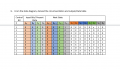
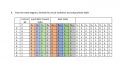
I am trying to construct a truth table for my SR Flip flop (SR flip-flops and an external input x, a circuit that will count modulo 10 (i.e. from zero to nine, then back to zero and repeat) can anyone let me know if I am on the right track
Attachments
-
 25.3 KB Views: 9