Facebook
 Google
 GitHub
 Linkedin
Hi all,
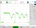
I've designed a discontinuous current mode Flyback converter. I'm now testing it with fixed loads. At max. load, it works fine: the output voltages are at the expected value and the PWM controller output signal consists of pulses with a constant width. At nominal load, I still get the correct output voltages but the PWM output signal is not as I would expect: it consists of one wide pulse followed by several much narrower pulses. When I look closely at the regulated output voltage, I can see it going up when the wide pulse occurs and then down until the next wide pulse occurs. I've attached a sketch of the signals. I hope it helps.
Is it a known issue? Where is the issue coming from?
Thanks in advance for your help! I'm currently completly stuck with this issue.
Cheers
Fred
Attachments
-
 27 KB Views: 12