 Facebook
 Google
 GitHub
 Linkedin
Hello,
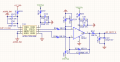
I use ACPL-C87B-000E as an isolation amplifier.
I am trying to measure ( OUT1_V_ISO) and isolate it.
The range of this point is 0 -1,5VDC.
The problem is: Even if I dont apply any voltage to OUT1_V_ISO, I measure 1,76V on VOUT- pin (6) of U14.(The reference is GDN2).
And I measure zero voltage on VOUT+ (pin7).
According to the datasheet Unity gain 1 V/V.
I would be very grateful if you could give any ideas.
Thanks,
Attachments
-
 66.8 KB Views: 31


