Is this regulator single or 3 phase ?

Thread Starter

alisomay

Joined Jan 30, 2018
29
Sorry to keep the forum busy with such an easy matter.
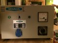
This is the first voltage regulator i got in to my hands.
Would you help me identify this voltage regulator?
Labels say,
Power: 2Kva
V1 : 150V
V2 : 220V
Frequency: 50Hz

Because there are 3 inputs to the circuit, i suspect that it is a 3 phase regulator. Can you confirm this?


First image is an overview, the third image contains the inputs, continues with the cables.
Thank you.
 

Attachments

ebp

Joined Feb 8, 2018
2,332
No, it's single phase. It is a variable autotransformer with a motor to set the position. I can't tell from the photos if the adjustment is automatic or manual. It looks like there may be a circuit board that might make it automatic, but if it does it will almost certainly be limited in how precisely it controls the output so that the motor is not constantly moving the rotor back and forth.

I don't understand what the 150V 220V is all about. I suspect it means it is designed to deliver 150 volts output from 220 volts input, or it may be the other way around. There is a tap on the winding which would be necessary for the latter case but not the former.
 

MaxHeadRoom

Joined Jul 18, 2013
28,681
Appears to be 1phase to me.
Maybe dual voltage supply.
The three inputs I believe are for some kind of auto transformer arrangement according to the way it is connected to the toroidal transformer style object.
Max.
 

Thread Starter

alisomay

Joined Jan 30, 2018
29
So by connecting the ground the right place, i can try to measure voltages between terminals without a load with different connection configurations? Sounds logical to me i'll try now.
 

Thread Starter

alisomay

Joined Jan 30, 2018
29
Second try,
Terminal 1 - Live
Terminal 2 - Floating
Terminal 3 - Live
Terminal 4 - GND

Circuit breaker trip :)
It looks very clean and no burned parts or bad joints.
I'll troubleshoot it in the morning probably something is broken.
 

Thread Starter

alisomay

Joined Jan 30, 2018
29
The regulator part has a short somewhere i'll try to find it.
The back connectors are input and output.
It is mono phase.

My findings are these. Thank you.
 

MisterBill2

Joined Jan 23, 2018
18,462
Making some effort to actually trace out the circuit would be far better than just connecting power to terminals to see what happens. The device was constructed for some purpose and so someplace there should be a description of what it is claimed to do, and how to connect to make it do that. It does not look so terribly complex but what the circuit could be traced out. The variable transformer has a start, an end, and the variable tap, and it also has a fixed tap as well. So the remaining question is what do you hope to have it do for you? At 2KVA it could be the basis for a medium-large electrical experimenter's power supply. It could also be converted into several pounds of scap metal with an incorrect power connection. Thus, a bit of research would be prudent.
 

Thread Starter

alisomay

Joined Jan 30, 2018
29
You are totally right. I actually called the company of this device and i learned that actually the connectors at the back of it are not only input but input and output. They wired the same output to the front side also. I narrowed down the problem to the regulator circuit because the thru mode is working properly.
It is just a bit hard to debug this circuit for me because it has no schematic. I go with the continuity test and measuring DC resitances to spot the transformer taps. With a little more time and a paper maybe i can achieve to fix this. As you say it doesn't look complex. My fear is i hope the short is not in the motor.
 
Top