Is this rectifier circuit abnormalities or normal?

Thread Starter

Exjay

Joined Nov 19, 2015
196
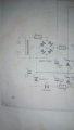
I tried building a rectifier circuit as below. I got a voltage of about 24v before placing C1. After C2, I got 35-40v. I got about 35v in C3. Is this normal? Again, I want to supply 20v through zener to an IC positive changes rail and -2v to the negative rail. I need help with the design.
 

Attachments

crutschow

Joined Mar 14, 2008
38,505
A rectifier-capacitor supply will give an unloaded output voltage near the peak AC voltage or 1.4*24-1.4V = 32Vdc.

How much current do you need from the two voltages?
 

Thread Starter

Exjay

Joined Nov 19, 2015
196
The IC should not consume more current. Pls I didn't see the current limit in the data sheet of LM723
 

Thread Starter

Exjay

Joined Nov 19, 2015
196
I used a 24rms transformer. I'm a beginner and I'm taking things slow for better understanding.
 

Thread Starter

Exjay

Joined Nov 19, 2015
196
Answer please. In designing the zener circuit would I use the calculated 24v or use the 35v after using a filter.
 
Top