Is this circuit ok for charging SLA gel cell batteries?

Thread Starter

uraniumhexoflorite

Joined Oct 23, 2016
216
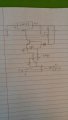
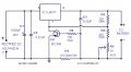
I have a 12 volt 17.5 amp hour gel cell SLA battery and the charger I was using died on me. I want to get it charged asap to minimize the amount that the battery sulfates. I remember seeing this schematic online and many others that are similar to it and I thought it may just be easier to assemble this one since I have the parts lying around. Since there is a lot of conflicting information online on how to charge batteries, I just wanted to make sure that this circuit is ok for me to use for an SLA that is occasionally subject to shallow cycles and very rarely to deeper cycles. I was also thinking about charging the battery at less than 0.1C. Maybe 0.05C. Since I don't use the battery often, it is ok for it to charge slowly as long as that doesn't damage the battery.
Here's a link to the page the circuit is from.
http://www.circuitstoday.com/lead-acid-battery-charger
Thanks in advance for the help! :)
 

Attachments

ebp

Joined Feb 8, 2018
2,332
That circuit should work quite well. The current limiting won't be very accurate, but that isn't important. For "float" charging, where the battery is constantly connected to the charger it is important that the voltage be very accurately regulated. 2.25 to 2.3 volts per cell is the usual recommendation for "room temperature." Be very careful not to connect the battery in reverse polarity.

form Panasonic:
https://na.industrial.panasonic.com...oads/files/panasonic_vrla_chargingmethods.pdf
Panasonic has been making SLA batteries for many years, so their recommendations are quite trustworthy.
 

Thread Starter

uraniumhexoflorite

Joined Oct 23, 2016
216
Is temperature compensation a necessity? I plan to charge the battery at a lower current since it isn't used often and lower current would allow me to also fit a smaller heat sink to the LM317.
 

ebp

Joined Feb 8, 2018
2,332
The temperature compensation is for the battery charging voltage. The voltage must be reduced as the battery temperature rises. Without compensation a battery operating at very low temperature will not be fully charged and one at high temperature will be overcharged. Overcharging is a very bad thing to do with a "sealed" battery because you move from charging the cell to electrolyzing the water in the electrolyte - producing hydrogen and oxygen gas. If the pressure builds sufficiently, the safety valves will open. That means water is forever lost from the electrolyte, and there isn't a lot of excess water in a sealed battery to begin with. Sometimes venting also blows some liquid electrolyte out, too. There is no universal agreement on the correct temperature compensation coefficient or where the compensation curve should "go flat."

If you always have your battery at a fairly constant temperature you don't need compensation but you should adjust the float voltage to that which is appropriate for the temperature. If the battery temperature can change rapidly or by a large amount when you aren't around to adjust the voltage manually, temperature compensation is a good idea. Ideally the temperature sensor is closely coupled to the battery. At low charge and discharge rate, the internal temperature of the battery won't be very different from nearby ambient temperature.
 

crutschow

Joined Mar 14, 2008
38,503
Below are the LTspice simulations of the circuits in posts #1 and #3.
The battery is simulated by a large capacitor.

The first is simpler but has a rapid drop in charge current to a very low value as the battery voltage increases towards the final value.

The second has a fairly constant charge current until the end voltage is reached.
In that circuit R4 determines the charge current.

I prefer the second circuit.


upload_2018-10-27_13-32-48.png

upload_2018-10-27_13-49-6.png
 

Thread Starter

uraniumhexoflorite

Joined Oct 23, 2016
216
For the 2nd circuit I was thinking that I would add an op amp that would activate an LED when the voltage reached a pre determined value (I was thinking 13.6 or something like that) to indicate that the charging was almost done. Is this the best easy way to do this or is there some other easy way to do it?
 

Thread Starter

uraniumhexoflorite

Joined Oct 23, 2016
216
So something like this? I was thinking that the resistors on the op amp could be 10k or something similar to that as long as they are all the same except for the resistor in series with the LED. I would determine that based off the voltage supplying the op amp.
 

Attachments

Thread Starter

uraniumhexoflorite

Joined Oct 23, 2016
216
Also what wattages would you suggest for the resistors in the main circuit? I was thinking 1/8 or 1/4 watt for all except the 1 ohm resistor and 2 to 5 watts for the 1 ohm resistor.
 

crutschow

Joined Mar 14, 2008
38,503
Here's my take on adding a charge-done LED.
I used an LM339/393 comparator to detect the voltage and turn on the LED
I also added a power-on LED (D1), which does double-duty as a voltage reference for the comparator trip point.
The values of R5 and R8 can be changed as needed to get the desired LED current for the particular input (V+) voltage you will have.

The shown values for R6 and R7 give a value of about 400mV for the trip point in the simulation.
The voltage can be varied as needed by changing those resistance values, depending upon the actual forward voltage of the selected LED.
All resistors can be low power except the 1 ohm resistor should be ≥1W.

upload_2018-10-29_8-12-25.png
 
Last edited:

ebp

Joined Feb 8, 2018
2,332
It's still too much for an LM317, there will be losses and the battery will get drained faster. It's better to use a buck regulator.
No it is not. The regulator circuit has a current limit of about 1.2 A which is fine for the 317 if it has an adequate heatsink and could easily be reduced by changing a single resistor. The battery is being charged, not drained.
 

Thread Starter

uraniumhexoflorite

Joined Oct 23, 2016
216
Would the circuit work with 18 volts instead of 16? Would it need the current limiting resistor to be more resistive?
Edit: I was also unable to find any 240 and 2400 ohm resistors. Would it be ok to substitute 220 and 2200 respectively? Is it also ok to replace R5 with a 2200 ohm resistor? Could I substitute the op amp with an LM358? I literally have 100 of those things.
 
Last edited:
Top