 Facebook
 Google
 GitHub
 Linkedin
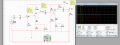
Hello everyone, im working on this common emitter amplifier for my lab on multisim as shown below. I designed it, and measured all the voltages as shown. Now, I know that the purpose of this amplifier is to take the shown AC input signal, and amplify it into a larger AC signal at its output. I also understand what the coupling capacitors are preventing DC signals from passing from the stages where DC biasing is required. So I think I understand the general purpose of this amplifier (correct me if im wrong please). Now, im confused on a few things:
- Is the bypass capacitor simply sending AC signals to ground? I used to think that when biasing the transistor so it can amplify the AC signal, we need to send AC signals on that portion to ground so that the DC biasing doesnt have any ripples. So since capacitors have low resistance to AC signals, the AC signal will just take the path of least resistance to ground. Is this correct, or am I thinking the wrong way?
- What is the second resistor exactly doing under the emitter? I think that its a good idea to have that split resistance there because if we only had one resistor in parallel with the bypass capacitor, it would short out with all of the AC signals that go through it, making the DC bias not stable and what not.Again please correct me if my understanding is flawed.
-My last question is about the amplifier gain. Now, as shown in the voltage measurements I simply took the AC input Voltage, and the Output voltage and since the gain is output/input, i just did that. I did 2.08 V / 0.02 V and got an answer of 86.66. Now, I also measured the input voltages peak to peak at each of the stages, and also at the end of each stage. For the first stages gain I get 11 because I did 280mV / 25.4mV. Then for stage 2 i did the same procedure and got 2.08V/ 0.28V and I get 7.43. Now, if i multiply the gains of these two stages together I should get the overall gain of 86.66 like I measured earlier, but I get 81.73 instead. Not the same exactly but close enough for it to be right, is this the correct procedure? also just to make sure voltage peak to peak is the AC voltage correct? since when I measure with the voltage tool I also get a regular voltage as shown.
I also provided the waveform measuring the input vs output. As we can see, the input AC signal is the same at the output except amplified, so i believe the amplifier did its job!.
I forgot to mention. Im measuring the output across the R6 resistor. thank you everyone.
Attachments
-
 39.7 KB Views: 14
 -
 342 KB Views: 11


