Facebook
 Google
 GitHub
 Linkedin
Hi there,
After scouring the forum for what seems hours and hours, I'm still no closer to finding the exact answer I'm looking for...
Here's my dilemma:
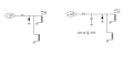
I'm running a 12volt supply to activate a solenoid. Within the initial wiring I have a push button switch (obviously to allow me to activate the solenoid).
In tandem with the solenoid I have a relay. Why? Because as I activate the switch, the solenoid activates and so does the relay. In turn, the relay then completes a switch to a PC keyboard encoder (if you're not sure what one of these are, it doesn't matter, because I simply need to know...>>)
The keyboard encoder requires/requests NO voltage. It simply needs the connection complete (as what a standard button would do). This is why I thought the relay would be ideal. Unfortunately, I've since found that current flowing through a relay coil creates a magnetic field which collapses suddenly when the current is switched off. The sudden collapse of the magnetic field induces a brief high voltage across the relay coil which knocks out my keyboard encoder.
So guys, what do I need to implement into my design to ensure the relay doesn't send any voltage through it's COM/NC connections? A diode? A resistor? And what type and where would it go to protect my encoder?
I've tried to find the answer for AGES, so all help will be greatly appreciated.
Thanks.
After scouring the forum for what seems hours and hours, I'm still no closer to finding the exact answer I'm looking for...
Here's my dilemma:
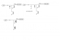
I'm running a 12volt supply to activate a solenoid. Within the initial wiring I have a push button switch (obviously to allow me to activate the solenoid).
In tandem with the solenoid I have a relay. Why? Because as I activate the switch, the solenoid activates and so does the relay. In turn, the relay then completes a switch to a PC keyboard encoder (if you're not sure what one of these are, it doesn't matter, because I simply need to know...>>)
The keyboard encoder requires/requests NO voltage. It simply needs the connection complete (as what a standard button would do). This is why I thought the relay would be ideal. Unfortunately, I've since found that current flowing through a relay coil creates a magnetic field which collapses suddenly when the current is switched off. The sudden collapse of the magnetic field induces a brief high voltage across the relay coil which knocks out my keyboard encoder.
So guys, what do I need to implement into my design to ensure the relay doesn't send any voltage through it's COM/NC connections? A diode? A resistor? And what type and where would it go to protect my encoder?
I've tried to find the answer for AGES, so all help will be greatly appreciated.
Thanks.

")