Is it better to buy a bench PSU, or build one?

Ian0

Joined Aug 7, 2020
13,299
You mean 4 outputs total? Or 2?
Just two - a fixed +12V and -12V would be perfect for most audio small-signal work. You may not even need it variable.
That is one you could make yourself as you could just use a 7812 and 7912

Some 0-30V variable PSUs have additional +12V and +5V outputs such as this one, which is handy if you are running some logic as well
https://www.rapidonline.com/rapid-ep-603-209g-triple-out-0-30v-5v-12v-2-5a-ana-psu-85-1707
but I've not seen one with a -12V.
 

SamR

Joined Mar 19, 2019
5,542
When you get into op-amps they require in addition to the circuit power a + & - voltage supply for the op-amp itself. So that's 3 different power supplies. Here is a DIY dual adjustable +/- voltage kit that says up to 40V but actually comes with only 30V electrolytic capacitors. Since most op-amps have a MAX +/- 18V rating this fits the bill. It does require a fused transformer and power cord in addition to the kit. I put this together in under an hour and was pleased with the quality of the design and the parts were on spec except for the 30V caps. The price has gone up a few dollars but the free shipping makes it still a good deal. It is screwdriver adjustable for voltage but no current limiting or display. Nothing fancy about it, just cheap and serviceable. You can't buy the parts as cheap as this is. You will have to spend another 20-30$ for a XFMR, fusing, and cord. I used a 120/240/28/28 dual primary and seconday XFMR with it and unloaded get ~24V +/- out of it.
 

Thread Starter

Joe Stavitsky

Joined Apr 5, 2020
141
I mean, obviously they are charging to provide sufficient current to the transistors (voltage regulators) and I assume they also block noise, but I don't know which equations are relevant for how they are sized and why there are 2 sets on each side of the transistors
 

MrChips

Joined Oct 2, 2009
35,249
C1 and C2 are called reservoir capacitors. The purpose of these are to hold the voltage at AC line frequency 50/60Hz (x2 for a fullwave rectifier) steady in between charge and discharge cycles. What do I mean by that? The load will demand an average current given by:

Iavg = Vavg / Rload

The rectifier diodes do not conduct all the time. The diodes conduct only when the peak of the AC input exceeds the voltage at the load. Hence we get an output Vavg with ripples at two times mains frequency.

In a power supply design we want to pay attention to the ripple voltage. You cannot demand that the ripple voltage be as low as possible because that is unachievable in an unregulated PSU such as this one. So we seek a compromise. How much ripple voltage are we willing to accept? That is anyone's guess. Luckily we can estimate the ripple voltage as follows:

Vripple = I / 2fC

where I = load current
f = line frequency x 2
C = reservoir capacitor

As an example, suppose
I = 1A
f = 60Hz
C = 1000μF = 0.001F

Vripple = 1 / (2 x 60 x 0.001) = 1000/120 = 8V

Increase C = 2000μF, Vripple = 4V

Now, since we are going to follow this with a 3-terminal linear voltage regulator, we make sure that the minimum input voltage is higher that the minimum rerquired by the regulator. Every linear voltage regulator requires headroom which we call the dropout voltage. A typical dropout voltage is about 2V.

Hence the input for 12V regulation has to be at least 12V + dropout + ½Vripple = 16V.

As you can see, the value of the reservoir capacitor determines the ripple voltage.
(The peak current through the diode also increases as we increase the value of the capacitor. That is yet another story.)

The function of the smaller value capacitor comes next.
 

hrs

Joined Jun 13, 2014
539
It's just an example I had on hand to illustrate the point. They turned into 15V regulators that draw minimal current. Do you know the reason for the second set of diodes? Output short or the like. That would be more interesting to argue about.
 

SamR

Joined Mar 19, 2019
5,542
There is one thing I am a bit fuzzy on and that is the combination of post-rectifier smoothing caps and voltage regulators such as the LM317. I never got a good feel for what exactly was called for as a smoothing cap in series with a regulator that also smoothes. Then there is the question as to how much smoothing is required in which circumstances? Let's limit this to full wave bridge rectification.
 

dl324

Joined Mar 30, 2015
18,481
Then there is the question as to how much smoothing is required in which circumstances? Let's limit this to full wave bridge rectification.
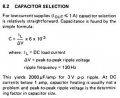
There's a formula for estimating the filter cap value based solely on load current. This is from a Nat Semi Voltage Regulator Handbook (1980):
clipimage.jpg
What it doesn't mention is that the value also depends on the peak rectified and how much headroom the regulator has.

If you had a 3.3V regulator and, for some silly reason, used a 24V secondary, you wouldn't need as large of a filter cap as the formula would indicate. The key is to never let the regulator input voltage go low enough to cause it to stop regulating.

Values for half wave rectification would need to be larger because there's more time for the capacitor voltage to decay.

EDIT: You should also give consideration to ripple voltage on the cap which would cause heating.
 
Last edited:

MrAl

Joined Jun 17, 2014
13,833
Building a PSU is one of the few "academic" projects I'm willing to consider. I don't see it taking me too long, and I can probably make something nice to look at. However, I may consider buying one at the $300-$500 pricepoint if I'm convinced that there are major advantages. Thoughts?

Many thanks in advance

Joe
Hello,

I am coming in a little later to this thread so let's see how it goes.

What kind of output voltage current and power do you need?
It is always easier to buy one, i bought several over the years, that put out some decent current at a decent voltage, 10 amps at 0 to 30 volts. It is not easy building one like that and still get a decent output that is clean and does not waste too much power.

On the other hand, i also build several in the past. The one that comes to mind first is the one that i wanted to do some special testing with and i needed 1mv adjustment and absolutely stable output voltage over time and not too big of a temperature range, so i threw together a high current LM317 like supply but added a special regulator circuit using an op amp or two and some voltage reference diodes. The adjustment was tricky because i wanted to be able to change from say 12.000v to 12.001 volts for example, and keep it like that for hours. But a little thinking and a little experimenting and it works like a charm. I dont use it that much anymore but it was cool to build and test and use.
The parts were quite cheap too with the op amp being around 50 cents (USD) and reference diodes cheap too and everything else cheap, but at one point i did consider going to a higher speed op amp that is pin for pin compatible with the cheap op amp so i could get faster load regulation during a load change. The new op amp would be about 5 to 7 dollars (USD) but that would be the most expensive part in the whole thing.

So sometimes you have to build one yourself because trying to buy one might cost a fortune, but if you just need a run of the mill one it is probably best to buy one. Just make sure the pots they use are good quality pots because if not they will wear out pretty fast and then you will get erratic voltage and current adjustment until you dig in and replace the pots with better ones.
 

SamR

Joined Mar 19, 2019
5,542
if you just need a run of the mill one it is probably best to buy one. Just make sure the pots they use are good quality pots
All of the newer bench models I've looked at use digital rotary encoders and digipots. The kits however use a chinesium knockoff of the Bourne trimpot. Which so far I've had no problem with...
 

MrAl

Joined Jun 17, 2014
13,833
All of the newer bench models I've looked at use digital rotary encoders and digipots. The kits however use a chinesium knockoff of the Bourne trimpot. Which so far I've had no problem with...
Hi,

Oh that's good news. I remember one in particular that i bought and a neighbor bought the same one at the same time, same order, for 2 units. A short time later the pots on the neighbors started to go so i bought that one from the neighbor too and then replaced all the pots on both units and added better reverse current protection to one of them. I got the new pots from Digikey.
I was lucky to find ones that would fit in there it was very tight.
I added the reverse polarity protection on one of them because i used it to charge lead acid batteries and one time i reversed the connections and blew out the protection diode that was stock in the units. It was hard to find that diode too it was buried deep. I didnt think it was good enough so i added better reverse polarity protection.
The units are pretty decent other wise, they each put out 10 amps at up to 30 volts DC with course and fine current limit and voltage adjust, so that's four pots per unit :)
 
Top